Diffraction from crystals
Co-author: Bente Lebech, Technical University of Denmark
In crystalline solids, the atoms are organised in a regular pattern. We will here show how the interference between neutrons scattered elastically from atoms in a crystal leads to scattering only at particular "non-small" values of \(\bf q\). This type of scattering is known as diffraction and is governed by the celebrated Bragg law.
By analyzing diffraction patterns from powders (a sample of randomly oriented \(\mu\)m- or nm-sized crystallites) or single crystals, it is possible to determine the crystal structure, lattice parameters, and atomic positions in crystalline materials. Neutron diffraction on powders and single crystals can be used also to determine magnetic structures, as briefly described on the page Magnetic neutron scattering.
Basic crystallography
We here give a brief introduction to the scientific field of crystallography, which is the study of the atomic arrangements in crystals, often seen in connection with organic and inorganic chemistry, mineralogy, or molecular biology (protein crystallography). Crystallography is a vast field in itself, and here we only touch the basics of it.
Crystal structures consist of ordered arrangements of groups of atoms (or molecules) placed within two- or three-dimensional space filling lattices. The overall symmetry of a crystal structure is determined by the underlying crystal lattice and by application of certain symmetry elements. In mathematical terms, these symmetry elements are called congruent, isometric transformations. They may be translations, rotations and screws (direct congruent) or inversions, reflections and glides (opposite congruent). See Ref. [1] for further details.
Lattice vectors
In a regular crystal, the atoms are arranged in a three-dimensional periodic structure; a lattice. It is possible to divide the crystal into a (large) number of identical unit cells, each containing one or more atoms. The position of a unit cell can be determined by just three integers, \(n_a\), \(n_b\), and \(n_c\):
\begin{equation}\label{eq:r_unitcell} {\mathbf r} = n_a {\mathbf a} + n_b {\mathbf b} + n_c {\mathbf c} , \end{equation}
where the vectors \({\bf a}\), \({\bf b}\), and \({\bf c}\) are called the lattice vectors. The length of the lattice vectors are called the lattice constants, \(a\), \(b\), and \(c\), respectively. Usually, but not always, the order is chosen so that \(a \leq b \leq c\).
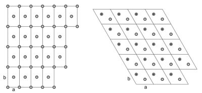
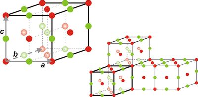
Two-dimensional crystal lattices are simple to visualise, and two examples are shown in Figure xx--CrossReference--fig:2Dcrystal--xx. More realistic crystal lattices are three-dimensional, where the shape of a unit cell is a parallelepiped spanned by the three (right handed) lattice vectors, as shown in Figure xx--CrossReference--fig:crystal--xx. The angles in the unit cell are defined with \(\alpha\) being the angle between \({\bf b}\) and \({\bf c}\), \(\beta\) being the angle between \({\bf c}\) and \({\bf a}\), and \(\gamma\) the angle between \({\bf a}\) and \({\bf b}\). The volume of a unit cell is given by the volume product
\begin{equation}\label{dummy1375896635} V_0 = {\mathbf a} \cdot {\mathbf b} \times {\mathbf c}. \end{equation}
This product is positive due to the right-handedness of the lattice vectors.
The reciprocal lattice
It is convenient to define the reciprocal lattice vectors by
\begin{equation}\label{dummy1014747689} {\mathbf a}^* = \dfrac{2 \pi}{V_0} {\mathbf b} \times {\mathbf c} , \qquad {\mathbf b}^* = \dfrac{2 \pi}{V_0} {\mathbf c} \times {\mathbf a} , \qquad {\mathbf c}^* = \dfrac{2 \pi}{V_0} {\mathbf a} \times {\mathbf b} . \end{equation}
Each reciprocal lattice vector is perpendicular to two of the three real-space lattice vectors:
\begin{equation}\label{dummy60639701} {\bf a}^* \cdot {\bf b} = {\bf a}^* \cdot {\bf c} = 0 , \qquad {\bf b}^* \cdot {\bf a} = {\bf b}^* \cdot {\bf c} = 0 , \qquad {\bf c}^* \cdot {\bf a} = {\bf c}^* \cdot {\bf b} = 0 , \end{equation}
whereas
\begin{equation}\label{dummy1842204777} {\bf a}^* \cdot {\bf a} = 2\pi , \qquad {\bf b}^* \cdot {\bf b} = 2\pi , \qquad {\bf c}^* \cdot {\bf c} = 2\pi . \end{equation}
The three reciprocal lattice vectors span the reciprocal lattice, where a general lattice point is given by
\begin{equation}\label{eq:rlv} {\boldsymbol\tau}_{hkl} = h {\mathbf a}^* + k {\mathbf b}^* + l {\mathbf c}^* . \end{equation}
The Miller indices \(h\), \(k\), and \(l\) are here integers. The lattice spacing corresponding to a set of Miller indices is defined as the distance between lattice planes perpendicular to \({\bf\tau}_{hkl}\) and is given by
\begin{equation}\label{eq:latticespacing} d_{hkl} = \dfrac{2 \pi}{|{\boldsymbol\tau}_{hkl}|} . \end{equation}
From equation \eqref{eq:r_unitcell} and \eqref{eq:rlv}, we calculate the dot product between a general lattice vector and a general vector of the reciprocal lattice:
\begin{equation}\label{eq:lattice_phase_2pi} {\boldsymbol\tau}_{hkl} \cdot {\mathbf r} = 2 \pi (n_a h + n_b k + n_c l) . \end{equation}
This result will be used in later derivations.
It can easily be shown that the volume of the reciprocal unit cell is given by
\begin{equation}\label{dummy310262986} V_{\rm r} = \dfrac{(2\pi)^3}{V_0}. \end{equation}
It is possible to make a reciprocal space unit cell of volume \(V_{\rm r}\), which is centered around the origin and in which each point is located closer to the origin than to any reciprocal lattice vector. This cell is called the Brillouin zone and is discussed in detail in most textbooks on solid state physics[2].
Atomic positions in the unit cell
A particular simple class of lattices is the Bravais lattice, defined as a lattice where each unit cell contains only one atom. Hence, a Bravais lattice are found only among the pure elements, since each unit cell must contain at least one formula unit. In a Bravais lattice, the atomic positions are given directly by equation \eqref{eq:r_unitcell}.
By far, most lattices are non-Bravais lattices. Here, each unit cell consists of more than one atom, and their relative positions within the unit cell are given by their basis, denoted \(\bf\Delta\). The absolute position of the \(i\)'th atom in the \(j\)'th unit cell is thus
\begin{equation}\label{dummy404727957} {\mathbf r}_{i,j} = {\mathbf r}_j + {\boldsymbol\Delta}_i , \end{equation}
where \({\bf r}_j\) is the position of the \(j\)'th unit cell.
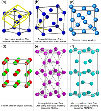
One often encountered example of a lattice with a basis is the body-centered cubic lattice (see Figure xx--CrossReference--fig:crystal_classes--xx). This lattice can be described as a simple cubic lattice of side length \(a\) with a two-atom basis. One atom is placed at \({\bf\Delta}_0 = (0,0,0)\), and the other at \({\bf\Delta}_1 = (1/2, 1/2, 1/2)\,a\).
Symmetry groups
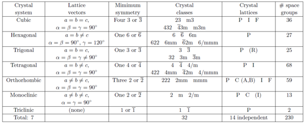
According to the symmetry properties, ordered arrangements of atoms are divided into 17 two-dimensional and 230 three-dimensional space groups. Below we describe the 7 groups of crystal lattices covering all three-dimensional space-groups sorted by decreasing symmetry. The meaning of the parenthesized letters after the lattice names will be explained later.
- Cubic: (P, I, or F). This is the class of highest symmetry and has a 4-fold symmetry. All lattice constants are equal, and the lattice vectors are mutually perpendicular. Thus, the unit cells are cubes: \(a=b=c\), \(\alpha = \beta = \gamma = 90^\circ\).
- Hexagonal (P). This is a crystal class with a 6-fold symmetry axis: \(a= b \neq c\), \(\alpha = \beta = 90^\circ\), and \(\gamma = 120^\circ\).
- Trigonal (R). This can be seen as an angular distortion of the cubic lattice. Trigonal structures are often described by hexagonal cells with the \(c\)-axis along the rhombic body diagonal: \(a=b=c\), \(\alpha = \beta = \gamma \neq 90^\circ\).
- Tetragonal (P or I). This class can be seen as a distortion of a the cubic crystal along one axis, keeping all vectors perpendicular: \(a=b \neq c\), \(\alpha = \beta = \gamma = 90^\circ\).
- Orthorhombic (P, C, I, or F). This is a further distortion of a tetragonal crystal, still keeping the unit vectors perpendicular: \(a \neq b \neq c\), \(\alpha = \beta = \gamma = 90^\circ\).
- Monoclinic (PB or PC). An angular distortion of an orthorhombic crystal: \(a \neq b \neq c\), \(\alpha = \beta = 90^\circ\), \(\gamma \neq 90^\circ\).
- Triclinic (P). The lowest symmetry class, where the lattice is a parallelepiped without any relation between axis and angles: \(a \neq b \neq c\), \(\alpha \neq 90^\circ\), \(\beta \neq 90^\circ\), \(\gamma \neq 90^\circ\).
Crystal structures and symmetries
The knowledge of the classification in 230 space groups is highly useful when determining crystal structures. Details of the symmetry aspects of these space-groups are collected in various versions of "The International Tables for Crystallography" (in this text abbreviated "IT")[3][4]-->. Here, we will give a rudimentary introduction to three-dimensional crystal structures and their classification. Furthermore describe how to interpret the information given in IT and how to use it when refining a crystal structure from real experimental or simulated diffraction data.
In its simplest form, a crystal structure is formed by placing one atom within a lattice and applying a number of symmetry elements which are consistent with the geometry of the underlying lattice to the coordinates of the first atom. Naturally, the symmetry of the structure increases with the number of symmetry elements. In [3], the site positions of atoms in the possible two- and three-dimensional space groups are listed according to the crystal lattices and the applied symmetry elements.
The space group with the lowest symmetry and space group number "1" is triclinic P1. Within the unit cell this space group has just one atom site position per atom type with coordinates \((x,y,z)\). The symmetry element is a translation of the unit cell or, equivalently, rotation by 360\(^\circ\). The space group with the second lowest symmetry (translation of the unit cell) and space group number "2" is also triclinic \(\text{P}\bar{1}\), but in addition to translation symmetry it has an inversion centre. Hence, within the unit cell this space group has two atom site positions per atom type with general coordinates \((x,y,z)\) and \((-x,-y,-z)\).
The space group with the highest symmetry and space group number 230 is cubic \(Ia\bar{3}d\). Within the unit cell this space group has 96 atom sites per atom type. The set of 96 coordinates \((x_i, y_i, z_i)\) are generated by the coordinates of a single atom site per atom type \((x_1,y_1,z_1)\) after application of the space group symmetry elements (see the section How to use the information in IT).
Each of the space group listings in IT are described by a number and a combination of letters and numbers. The numbers represent the rotational symmetry (1-, 2-, 3-, 4- or 6-fold rotation) of the space group and small letters represent certain symmetry elements (e.g. m for mirror line or plane and represent 1- or 3-fold rotations plus inversions through centre). The first letter is always a capital. It indicates if some vectors in the crystal lattice are related in a non-trivial way and possess symmetry other than the identity. These letters are shown in parenthesis in the listing (1 to 7) of the lattice types given above. The letter P means primitive, i.e. the only symmetry imposed by the lattice is the identity, F means face centered, i.e., for the smallest possible unit cell, the lattice symmetry automatically generates atom sites at \((x,y,z) + \bar{d}_f\) where \(\bar{d}_f\) equals half a face diagonal. The letter I means body centered, which is a translation from German "innen zentrierte", i.e. the lattice symmetry automatically generates atom sites at \((x,y,z) + \bar{d}_b\) where \(\bar{d}_b\) equals half a body diagonal. For more complicated crystal lattices, other capitals are used to signify specific lattice related symmetries. The most important ones are R (rhombohedral) used for trigonal space groups and C (base centered) used for some orthorhombic and monoclinic space groups.
Figure xx--CrossReference--fig:crystal_classes--xx(a) shows a body centered cubic (bcc) structure. Figures xx--CrossReference--fig:crystal_classes--xx(b) and (d) illustrate face centered cubic (fcc) structures with one and two types of atoms, respectively. Figures xx--CrossReference--fig:crystal_classes--xx(a) and (b) also represent two of the 14 three-dimensional Bravais lattices. By definition, Bravais lattices contain only a single atom per unit cell which is obviously not the case for the cubic structures shown in Figure xx--CrossReference--fig:crystal_classes--xx(a) and (b). However, the smallest space filling units for fcc and bcc mono-atomic crystals are not cubic, but rhombohedral as shown by the true yellow unit cell in Figure xx--CrossReference--fig:crystal_classes--xx(a) and indicated by the three yellow rhombohedral axes shown in Figure xx--CrossReference--fig:crystal_classes--xx(b). The bcc and fcc Bravais structures are to be considered in more detail in the problem Bragg scattering from Bravais lattices. Certain properties of structures with non-Bravais lattices will be considered in the problem Bragg scattering from non-Bravais lattices.
Another important structure is the hexagonal closed packed (hcp) lattice, which is a cell with a two-atom basis. Regarding the hcp lattice, it is important to notice that the distance between all nearest neighbour atoms are equal, and that it represents the closest possible packing of spheres (a property it shares with the fcc lattice). The hcp crystal will also be treated in the problem Bragg scattering from Bravais lattices.
The crystal classes and space groups
To provide a systematic overview, we will show Table xx--CrossReference--tab:crystallographytable--xx that contains the 7 crystal systems, the 14 crystal lattices, the 32 crystal classes, and how they are distributed on the 230 space groups. This table should be considered a "roadmap" to explore the world of crystallography, as presented in detail in IT and a lot of other places in literature.
How to use the information in IT
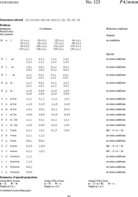
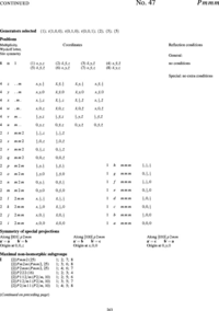
To refine diffraction data with standard programs, you need information about the possible atom positions in the simulated structure and their approximate occupancies. An explanation of how to obtain this information by means of "IT" is given in the following and can be used to solve Simulation project: A powder diffractometer.
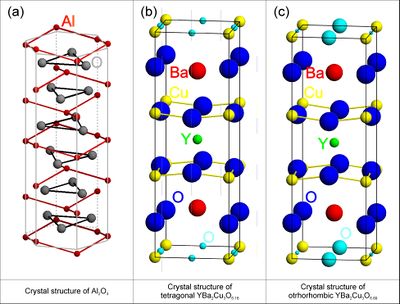
Before attempting a structure refinement, you will usually know the chemistry of your sample and have a rough idea about the crystal structure from other works (publications or databases) either obtained in the form of X-ray or neutron diffraction experimental data or, more unusual, from clever guesses. If the structure is known from publications the information may be in the form of a space group name or number. This is, e.g, the case for the tetragonal phase of the high-temperature superconductor YBa\(_2\)Cu\(_3\)O\(_{6+x}\) shown in Figure xx--CrossReference--fig:crystal_classes2--xx(b) for \(x = 0.18\), (P4/mmm, (\(D^1_{4h}\)), or #123, see Figure xx--CrossReference--fig:ITpage2--xx) with lattice parameters \(a = b \neq c\) and \(\alpha = \beta = \gamma = 90^\circ\). The coordinates of the atoms are called site positions and written in an abbreviated form which will be described shortly. For YBa\(_2\)Cu\(_3\)O\(_{6+x}\) the site positions are: Y-atoms at (\(1d\)), Ba-atoms at (\(2h\)), Cu-atoms at (\(1a\)) and (\(2g\)), and O-atoms at (\(2f\)), (\(2g\)), and (\(4i\)).
Depending on the O-concentration, \(x\), and the temperature, YBa\(_2\)Cu\(_3\)O\(_{6+x}\) undergoes a structural phase change from the tetragonal structure to an orthorhombic structure. The corresponding description of the orthorhombic structure usually named YBa\(_2\)Cu\(_3\)O\(_{7-x}\) is shown in Figure xx--CrossReference--fig:crystal_classes2--xx(c) for \(x = 0.11\). The space group is Pmmm, (\(D^1_{2h}\)), or #47 (see Figure xx--CrossReference--fig:ITpage--xx) with lattice parameters \(a \neq b \neq c\) and \(\alpha = \beta = \gamma = 90^\circ\). The possible site positions for the atoms in YBa\(_2\)Cu\(_3\)O\(_{7-x}\) are as follows: Y-atoms at (\(1h\)), Ba-atoms at (\(2t\)), Cu-atoms at (\(1a\)) and (\(2q\)) and O-atoms at (\(1b\)) or (\(1e\)), (\(2q\)), (\(2r\)), and (\(2s\)).
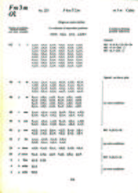
In order to explain the meaning of the parenthesised number/letter codes for the site positions quoted above, we use the space group example in Figure xx--CrossReference--fig:ITpage_old--xx. The figure lists the possible coordinates of atoms in the (fcc) cubic space group #225, \(Fm\bar{3}m\), or (\(O^5_h\)). The first column to the left shows the number of atoms with coordinates listed in columns 4 to 9. Because of the space group symmetry, one general atom coordinate set \((x,y,z)\) results in 191 other atom coordinates (192 general sites) unless there are special relations between \(x\), \(y\), and \(z\) (denoted special sites). Thus, \(x=y=z\) only results in 32 sets of atom coordinates. The 192 general sites are obtained by adding face centered coordinates to the 48 atom coordinates listed in the first group of coordinate sets in Figure xx--CrossReference--fig:ITpage_old--xx. The fact that the space group is face centered is indicated both by the F in the space group name and the four coordinates (0,0,0; 0,1/2,1/2; 1/2,0,1/2; 1/2,1/2,0)+ written just above the general site coordinates in Figure xx--CrossReference--fig:ITpage_old--xx. In the following we use \(N_G\) for the total number of positions at the general site and \(N_S\) for the total number of positions at a special site in a given space group.
In addition to the number of site atoms and coordinates, the second and third columns list a letter label and the point symmetry of the site. The letter label is assigned in alphabetical order where the site with the smallest number of site atoms is named "a". Hence, the special sites \(x=y=z\) and \(x=y=z=0\) and the general sites are named (\(32f\)), (\(4a\)), and (\(192l\)), respectively. The rightmost column contains information about space group or site imposed conditions for having non-zero structure factors. For the example in Figure xx--CrossReference--fig:ITpage_old--xx, the Miller indices for the space group allowed reflections must obey cyclic permutations of \(h+k=2n\) for general \((h,k,l)\); \(l+h=2n\) for \((h,h,l)\) and \(k,l = 2n\) for \((0,k,l)\). Additional rules apply for contributions to the structure factors from atoms at the special sites at (\(48g\)), (\(24d\)) and (\(8c\)).
In modern crystallography programs just one site position per atom type is needed as input because the remaining atoms are generated by the space group symmetry interactions included in the programs. The variables \((x,y,z)\) in general or special sites are replaced by numbers when calculating structure factors and intensities in programs like FullProf (refinable numbers) and Crystallographica (fixed numbers).
Occupancy
From the description above we can see that there is a maximum number of atoms at each site position in a crystal structure (element or isotope). For example, the maximum is 32 atoms of type "\(i\)" at the \(f\)-sites of space group #225 (see Figure xx--CrossReference--fig:ITpage_old--xx). However, some of the atom sites may be empty (vacancies) or partly occupied by different elements (an alloy) or isotopes. The most obvious way to define the occupancy, \(oc_{i,j}\) of a particular atom of type \((i,j)\) is to set it equal to one if all site positions are occupied by the same type of atoms and less than one for sites occupied by vacancies, different elements or isotopes which is equivalent to defining occupancy as the ratio between the total number of atoms in the unit cell at a given site and the site multiplicity of that site.
In the examples described in the section How to use the information in IT (Figure xx--CrossReference--fig:ITpage2--xx and Figure xx--CrossReference--fig:ITpage--xx), some of the oxygen sites are only partly occupied. If all sites in either compound were fully occupied, the chemical formula would be YBa\(_2\)Cu\(_3\)O\(_8\), and the number of formula units within the unit cell would be \(Z = 1\). Hence, according to the above definition of occupancy, \(oc = 1\) for all atoms. However, not all sites are fully occupied for the compounds described in the section How to use the information in IT.
In tetragonal YBa\(_2\)Cu\(_3\)O\(_{6+x}\) the \(2g\)- and \(4i\)-oxygen sites are fully occupied while the \(2f\)-oxygen site contain the excess oxygens. Therefore, the total number of \(2f\)-atoms in the tetragonal unit cell is \(Zx\) and the occupancy \(oc^{C}_{2f} = Zx/2\) because the site multiplicity of the \(2f\)-site is \(N_S=2\). In orthorhombic YBa\(_2\)Cu\(_3\)O\(_{7-x}\) either the \(1b\)-, \(1e\)- or both of these oxygen sites may be oxygen deficient while all other sites are fully occupied. If we assume that the \(1-x\) excess oxygen atoms are distributed between \(1-x-y\) atoms at \(1e\)-sites and \(y\) atom at \(1b\)-sites with site multiplicity \(N_S=1\), i.e. the corresponding occupancies will be \(oc^{C}_{1e} = Z(1-x-y)\) and \(oc^{C}_{1b} = Zy\).
For the examples above the ideal chemical formula represent structures with one formula unit per unit cell, but quite often this is not the case. One example could be Pr\(_{2-x}\)Ca\(_x\)CuO\(_4\) where the chemical formula has been reduced to represent one formula unit which must be repeated four times in order to represent all atoms in the unit cell, i.e. \(Z = 4\). The Pr- and Ca-atoms share the \(8f\)-site positions, and hence the chemical formula representing all atoms in the unit cell is Pr\(_{8-4x}\)Ca\(_{4x}\)Cu\(_4\)O\(_{16}\). Therefore the occupancies of the \(8f\)-Pr and -Ca atoms are \(oc^{C}_{Pr} = Z(2-x)/N_S\) and \(oc^{C}_{Ca} = Zx/N_S\) (\(N_S=8\)), respectively. The occupancies (\(oc^{C}_{i}\)) of the fully occupied Cu-site and the two different O-sites are all 1. This relatively simple way of assigning occupancies is used in e.g. Crystallographica (Cgraf), Powdercell (PCW) and many other programs which calculate structure factors and intensities of diffraction peaks.
In the refinement program FullProf the occupancies can be defined by the site multiplicity scaled by the concentration of the particular atom as given by the chemical formula, e.g. for fully occupied sites \(oc^{FS}_{i}=N_S\). This method is appropriate when refining single phase diffraction patterns, e.g. diffraction patterns without impurities. For multi-phase diffraction patterns this will generally result in incorrect scaling of intensities from the different phases and give erroneous estimates of phase contents. In order to ensure correct scaling of intensities between compounds when using FullProf for refining multi-phase diffraction patterns, the occupancies \(oc^{FS}_{i}\) for each compound must be scaled by the site multiplicity for the general site (\(N_G\)) of the compounds, e.g. \(oc^{FM}_{i} = oc^{FS}_{i}/N_G\). With these definitions, the occupancy for the \(2f\)-oxygen atoms in YBa\(_2\)Cu\(_3\)O\(_{6+x}\) is either \(oc^{FS}_{2f} = xN_S\) or \(oc^{FM}_{2f}=xN_S/N_G\) where \(N_G = 16\). Similarly, the occupancies for the \(1e\)- and \(1b\)-oxygen atoms in YBa\(_2\)Cu\(_3\)O\(_{7-x}\) is either \(oc^{FS}_{1e} = (1-x-y)N_s\) and \(oc^{FS}_{1b} = y N_S\) or \(oc^{FM}_{1e} = (1-x-y)N_s/N_G\) and \(oc^{FM}_{1b} = yN_S/N_G\) where \(N_G = 8\). However, it is strongly recommended to use the latter definition for occupancies even when refining single phase diffraction patterns.
- ↑ International Union of Crystallography, C. Giacovazzo (ed.), Fundamentals of Crystallography (Oxford University Press, 1992)
- ↑ Ashcroft and N.D. Mermin, Solid State Physics (Saunders, 1976)
- ↑ 3.0 3.1 3.2 3.3 3.4 International Union of Crystallography, Theo Hahn (ed.), International Tables for Crystallography, Volume A: Space-group symmetry (D. Reidel Publishing Company, Holland, 1987)
- ↑ 4.0 4.1 International Union of Crystallography, N. F. M. Henry and K. Lonsdale (eds.), International Tables for X-Ray Crystallography, Volume I Symmetry Groups (The Kynoch Press, Birmingham, UK, 1965)
- ↑ CSIS homepage, http://www.xtal.iqft.csic.es/Cristalografia/parte_03-en.html, December 2015.
Diffraction from crystalline materials
Our starting point for the description of crystal and powder diffraction is the expression for elastic scattering cross section for a system of nuclei, fixed in position, which we here repeat
\begin{equation}\label{eq:diffraction6} \dfrac{d\sigma}{d\Omega}\biggr|_{\rm nucl.} = \biggr|\displaystyle\sum_j b_j \exp(i {\mathbf q} \cdot {\mathbf r}_j)\biggr|^2 . \end{equation}
Our goal of this chapter is to describe the diffraction from crystals of macroscopic size and from nano-sized objects. Before this, we need to define some basic concepts in crystallography.
In the remainder of this section, however, we will expand equation \eqref{eq:diffraction6} to add the effect of material temperature on the scattered neutrons.
Scattering from vibrating nuclei
We release the artificial restriction that the nuclei are immobile. This means that the nuclear positions, \({\bf r}_j\) can change in time. We write the nuclear position as the sum of the average positions and a (small) time-dependent deviation:
\begin{equation}\label{eq:displacement} {\mathbf R}_j(t) = {\mathbf r}_j + {\mathbf u}_j(t) , \end{equation}
where the time average of the displacement vanish, \(\langle{\bf u}_j(t)\rangle=0\), in which the brackets denote the average. The full quantum mechanical treatment of equation \eqref{eq:displacement} results in an interaction between the neutrons and the quantised lattice vibrations, the phonons, which is studied by inelastic scattering. This is described on the Scattering from phonons page.
However, in this chapter we will consider only elastic scattering, so we can allow ourselves a more simple approach to estimate the effect of nuclear motion. Replacing \({\bf r}_j\) with \({\bf R}_j(t)\) in equation \eqref{eq:diffraction6}, we reach
\begin{align}\label{eq:diffraction7} \dfrac{d\sigma}{d\Omega} &= \left\langle \displaystyle\sum_{j,j'} b_j b_{j'} \exp(i {\mathbf q} \cdot {\mathbf R}_j(t)) \exp(-i {\mathbf q} \cdot {\mathbf R}_{j'}(t)) \right\rangle \\ &= \displaystyle\sum_{j,j'} b_j b_{j'} \exp(i {\mathbf q} \cdot {\mathbf r}_j) \exp(-i {\mathbf q} \cdot {\mathbf r}_{j'}) \left\langle \exp(i {\mathbf q} \cdot {\mathbf u}_j(t)) \exp(-i {\mathbf q} \cdot {\mathbf u}_{j'}(t)) \right\rangle . \nonumber \end{align}
The vibration term in the brackets implies that the phase of the scattered neutron has a slight random variation. This has the effect of reducing the scattering intensity. To quantify this, we assume that the displacements are uncorrelated, \(\langle{\bf u}_j(t){\bf u}_{j'}(t)\rangle=0\), and that the displacement amplitudes are isotropic and equal, \(\langle{\bf u}_j(t)^2\rangle=\langle{\bf u}_{j'}(t)^2\rangle\). Then, we perform a second order series expansion of the complex exponential functions:
\begin{align}\label{eq:diffraction8} \left\langle \exp(i {\mathbf q} \cdot {\mathbf u}_j(t)) \exp(-i {\mathbf q} \cdot {\mathbf u}_{j'}(t)) \right\rangle & \approx \left\langle \left(1-i {\mathbf q} \cdot {\mathbf u}_j(t) - ({\mathbf q} \cdot {\mathbf u}_j(t))^2/2\right) \left(1+i {\mathbf q} \cdot {\mathbf u}_{j'}(t) - ({\mathbf q} \cdot {\mathbf u}_{j'}(t))^2/2\right)\right\rangle \\ &\approx \left\langle 1-({\mathbf q} \cdot {\mathbf u}_j)^2 \right\rangle \nonumber\\ &\approx \exp(- \langle {\mathbf q} \cdot {\mathbf u}_j \rangle^2) .\nonumber \end{align}
The fourth (and higher) order terms in the series expansion agrees with the final result above, provided the displacement term \(\mathbf q \cdot {\bf u}_j(t)\) follows a normal distribution.
The Debye-Waller factor
The correction term equation \ref{eq:diffraction8} is widely known as the Debye-Waller factor:
\begin{equation}\label{eq:diffraction_DW} \exp(-2W_j) = \exp(-\langle{\mathbf q} \cdot {\mathbf u_j} \rangle^2). \end{equation}
In general, the Debye-Waller factor is site-dependent. However, one often uses the approximation where \(\exp(-2W_j)\) is the same for all \(j\). In this case, the elastic nuclear scattering cross section reads:
\begin{equation}\label{eq:diffract2} \dfrac{d\sigma}{d\Omega} \biggr|_{\rm nucl.} = \exp(-2W) \biggr| \displaystyle\sum_{j} b_j \exp(i {\mathbf q} \cdot {\mathbf r}_j)\biggr|^2 . \end{equation}
This implies that the expression in equation \ref{eq:diffraction6} for immobile nuclei still holds, with the correction that we need to multiply by the site-independent Debye-Waller factor, \(\exp(-2W)\).
At low temperatures, the temperature dependent displacement \({\bf u}_j\) has a small, but non-zero value due to zero-point fluctuations. This means that the Debye-Waller factor is always smaller than (but often close to) unity. All this is described in much more detail on the Scattering from lattice vibrations page and e.g. in the textbook by Squires[1].
Experimental consideration
The \(q\)-dependence of the Debye-Waller factor means that for large values of \(q\) (above 10 Å\(^{-1}\)), one generally prefers to cool the sample to avoid losing signal.
On the other hand, as \(q \rightarrow 0\) the Debye-Waller factor goes quickly to unity. This means that this temperature-dependent factor can be neglected in SANS, as already anticipated on the SANS page.
The scattering cross section for a crystal
We can now calculate the expression for the elastic neutron cross section, equation \eqref{eq:diffract2}, for a crystal, where we index the unit cells by \(j\) and the atoms within the unit cells by \(i\):
\begin{equation}\label{dummy1681181848} \dfrac{d\sigma}{d\Omega}\biggr|_{\rm nucl.\,el.} = \exp(-2W) \biggr|\displaystyle\sum_{i,j} b_i \exp(i {\mathbf q} \cdot ({\mathbf r}_j+{\mathbf\Delta}_i)) \biggr|^2 . \end{equation}
A small rearrangement of terms leads to the basic equation for crystal diffraction:
\begin{equation}\label{eq:cross_diffract_basis} \dfrac{d\sigma}{d\Omega}\biggr|_{\rm nucl.\,el.} = \exp(-2W) \left| F_{\rm N}({\mathbf q})\right|^2 \biggr|\displaystyle\sum_{j} \exp(i {\mathbf q} \cdot {\mathbf r}_j) \biggr|^2 , \end{equation}
where the nuclear structure factor, given by
\begin{equation}\label{eq:structurefactor} F_{\rm N}({\mathbf q})=\displaystyle\sum_{i} b_i \exp(i {\mathbf q} \cdot {\mathbf\Delta}_i), \end{equation}
depends only on the arrangement of the atoms inside the unit cell. We will later see that it is possible to determine \(|F_{\rm N}({\bf q})|^2\) experimentally and use it to deduce the atomic positions.
The lattice sum
To proceed, we like to calculate the sum over all unit cells: \(|\sum_j \exp(i {\bf q} \cdot {\bf r}_j)|^2\), also known as the lattice sum. Let us as a start approach this intuitively. If \(\bf q\) equals a reciprocal lattice vector, \(\bf\tau\), all the complex exponentials equal unity, c.f. equation \eqref{eq:lattice_phase_2pi}, and the squared sum must equal \(N^2\), where \(N\) is the number of unit cells. If \(\bf q\) is not a reciprocal lattice vector, many complex phases are present, and the sum should be small compared to \(N^2\) or vanish completely. Let us show formally that this is indeed what happens.
We assume that the lattice is "infinite", but we keep counting the number of lattice sites by \(N\). Hence, the squared sum can be rewritten
\begin{align} \label{eq:latticesum} \biggr|\displaystyle\sum_j \exp(i {\mathbf q} \cdot {\mathbf r}_j) \biggr|^2 &= \displaystyle\sum_{j,j'} \exp(i {\mathbf q} \cdot ({\mathbf r}_j-{\mathbf r}_{j'})) \\ &= \displaystyle\sum_{j,l} \exp(i {\mathbf q} \cdot {\mathbf r}_l) \nonumber\\ &= N \displaystyle\sum_l \exp(i \mathbf q \cdot {\mathbf r}_l) \nonumber \\ &= N \displaystyle\sum_j \exp(i \mathbf q \cdot {\mathbf r}_j). \end{align}
To perform the middle step, we utilize that the double lattice sum over \({\bf r}_j\) and \({\bf r}_{j'}\) can be transformed to a double sum over (i) one site, \({\bf r}_j\), and (ii) the difference between sites, \({\bf r}_l = {\bf r}_j - {\bf r}_{j'}\).
Now, equation \eqref{eq:latticesum} has the form \(|x|^2 = Nx\). Solving for the unknown lattice sum, \(x\), there are two possible solutions: \(N\) and \(0\). The value can only be \(N\) when all complex phases are multipla of \(2\pi\). Hence, this solution is found only when \(\bf q\) equals a reciprocal lattice vector; otherwise the zero solution must be chosen, as conjectured above. We can thus write equation \eqref{eq:latticesum} as a sum of Kronecker delta functions:
\begin{equation}\label{dummy1647858657} \displaystyle\sum_j \exp(i {\mathbf q} \cdot {\mathbf r}_j) = N \displaystyle\sum_{\boldsymbol\tau} \delta_{ {\mathbf q},{\boldsymbol\tau}} . \end{equation}
However, it is more convenient to write \eqref{eq:latticesum} in terms of Dirac delta functions. To do this, we write the sum as an unknown constant, \(c\), times the delta function:
\begin{equation}\label{eq:latticesum_c} \displaystyle\sum_j \exp(i {\mathbf q} \cdot {\mathbf r}_j) = c \displaystyle\sum_{\boldsymbol\tau} \delta ({\mathbf q} - {\boldsymbol\tau}) . \end{equation}
To determine the constant \(C\), we now integrate over one unit cell of the reciprocal lattice - a Brillouin zone. The right hand side can be immediately integrated to give \(c\), since the integration volume by definition contains exactly one reciprocal lattice vector. The left hand side is more elaborate; first we exchange sum and integration
\begin{equation}\label{eq:BZ_sum_int} \displaystyle\int_{\rm BZ} \displaystyle\sum_j \exp(i {\mathbf q} \cdot {\mathbf r}_j) d{\mathbf q} = \displaystyle\sum_j \displaystyle\int_{\rm BZ} \exp(i {\mathbf q} \cdot {\mathbf r}_j) d{\mathbf q} . \end{equation}
Now, the integral on the right hand side vanish if \({\bf r}_j \neq 0\). This can be seen by writing \({\bf r}_j = n_a {\bf a} + n_b {\bf b} + n_c{\bf c}\), \({\mathbf q} = h {\bf a}^* + k {\bf b}^* + l {\bf c}^*\), and integrate over \(h\), \(k\), and \(l\) (which are here no longer integers). The first one-dimensional integral is of the form \(\int_0^1 \exp(i h {\bf a}^* \cdot {\bf r}_j) dh = \int_0^1 \exp(i h n_a 2\pi ) dh = \delta_{n_a,0}\), and similar for the \(k\) and \(l\) integrals. Hence, the only contribution comes from the term with \({\bf r}_j = 0\). Therefore, the right hand side of equation \eqref{eq:BZ_sum_int} simply gives the volume of the Brillouin zone:
\begin{equation}\label{eq:BZ_integral} \displaystyle\sum_j \displaystyle\int_{\rm BZ} \exp(i {\mathbf q} \cdot {\mathbf r}_j) d{\mathbf q} = V_{\rm r} = \dfrac{(2\pi)^3}{V_0} = c . \end{equation}
Combining equation \eqref{eq:cross_diffract_basis}, \eqref{eq:latticesum}, \eqref{eq:latticesum_c}, and \eqref{eq:BZ_integral}, the final equation for neutron diffraction from a crystal becomes
\begin{equation}\label{eq:diffract} \dfrac{d\sigma}{d\Omega} \biggr|_{ {\rm nucl. el.}} = N \dfrac{(2\pi)^3}{V_0}\exp(-2W) \left| F_{\rm N}({\mathbf q})\right|^2 \displaystyle\sum_{ {\boldsymbol\tau}} \delta({\mathbf q}-{\boldsymbol\tau}). \end{equation}
The Bragg law
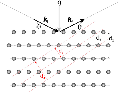
We now turn to the qualitative understanding of the diffraction cross section in equation \eqref{eq:diffract}. The delta-function in the equation gives rise to the so-called Laue condition
\begin{equation}\label{dummy642626747} {\mathbf q} = {\boldsymbol\tau} . \, \end{equation}
This can also be expressed in terms of the lattice spacings, \(d\), associated with the reciprocal lattice vectors (defined in equation \eqref{eq:latticespacing}): through the Bragg law:
\begin{equation}\label{eq:bragg} n \lambda = 2 d \sin(\theta) ,\, \end{equation}
where \(n\) is a positive integer and \(\theta\) is the angle between the incoming neutron direction and the lattice planes, see Figure xx--CrossReference--fig:bragg--xx. When scattering from a certain set of lattice planes, the scattering is specular, i.e. the incident angle equals the outgoing angle. The proof of equation \eqref{eq:bragg} is left as problem Simple Bragg scattering, the monochromator. The essence of the Bragg law is: Diffraction takes place only when equation \eqref{eq:bragg} is fulfilled. However, the reverse is not always the case. Sometimes no neutrons are diffracted even though the Bragg condition is fulfilled. This happens for reflections with \(|F_{\rm N}(\bf q)|^2=0\), as illustrated e.g. in problem Bragg scattering from Bravais lattices.
Experimental considerations
When a crystal is oriented to fulfill Bragg's law, one often talks about the reflected neutrons as a Bragg peak or a Bragg reflection. The neutron intensity in a Bragg reflection can be considerable, and at times the neutron beam needs to be attenuated in order not to saturate the detector(s). Saturation effects start at around \(10^4\) to \(10^6\) counts per second, depending on detector details. Most often, the attenuation is performed in the incident beam, often by using plastic sheets, possibly with boron content.
The angle between the incoming and outgoing beam in Figure xx--CrossReference--fig:bragg--xx is seen to be \(2\theta\). This is denoted the scattering angle and is the primary observable to be measured in an experiment. Usually in diffraction experiments, this angle needs to be determined to precisions of the order \(0.01^\circ\).
Integrals over the diffraction cross section
For the quantitative understanding of equation \eqref{eq:diffract}, the Dirac \(\delta\)-function in the cross section is the crucial part. The infinite amplitude of the \(\delta\)-function should not be taken litterally, since infinite amplitudes are unphysical. Instead, the \(\delta\)-function symbolizes that the scattering is strongly peaked at very small intervals around the reciprocal lattice vectors. The integral of the \(\delta\)-function does, however, have physical significance. Neutron scattering experiments are performed in non-ideal conditions, e.g. the incoming beam has a slight variation in wavelength (0.1\% - 1\%) and has a finite divergence (\(0.1^\circ\) - \(1^\circ\)). In most cases, this makes the observed intensity depend on the integral over the scattering cross section. We will here show how to perform integrals over the \(\delta\)-function. The derivation below is strongly inspired by Squires[1].
We will calculate the total cross section, i.e. the integral over all neutrons scattered by a particular Bragg peak.
\begin{equation}\label{eq:sigma_bragg_integral} \sigma_{\boldsymbol\tau} = \displaystyle\int \left( \dfrac{d\sigma}{d\Omega}\right)_{\rm nucl. el.,\, {\boldsymbol\tau}} d\Omega . \end{equation}
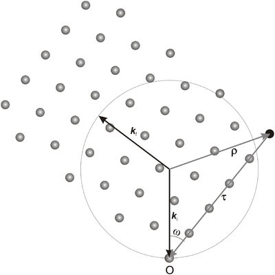
We consider a situation where the incoming neutron wave vector, \({\bf k}_{\rm i}\), and the reciprocal lattice vector in question, \(\bf\tau\), are fixed. The angle between \({\bf k}_{\rm i}\) and \(\bf\tau\) determines (one part of) the crystal orientation; this angle is most often denoted \(\omega\). The plane spanned by the two vectors \({\bf k}_{\rm i}\) and \(\bf\tau\) is called the scattering plane. The experimental geometry is often arranged so that the scattering plane is the horizontal plane. The factor \(\delta(\mathbf q-\boldsymbol\tau)\) in the scattering cross section in equation \eqref{eq:diffract} implies that the outgoing wave vector, \({\bf k}_{\rm f}\), also lies in the scattering plane, see Figure xx--CrossReference--fig:scatteringplane--xx. For very small crystallites, however, a spread of \({\bf k}_{\rm f}\) is seen, both in the in-plane and the out-of-plane directions. This is discussed in the section Diffraction from nano-sized systems.
The integral in equation \eqref{eq:sigma_bragg_integral} boils down to an integral over the \(\delta\)-function:
\begin{equation}\label{eq:delta_integral_1} \displaystyle\int \delta({\mathbf q}-{\boldsymbol\tau}) d\Omega = \displaystyle\int \delta(\boldsymbol\rho - {\mathbf k}_{\rm f}) d\Omega , \end{equation}
where we define \(\boldsymbol\rho = {\mathbf k}_{\rm i} - \boldsymbol\tau \). The only variable in the integral is the direction of \({\bf k}_{\rm f}\), since the requirement of elastic scattering gives \(|{\bf k}_{\rm i}|=|{\bf k}_{\rm f}|\). To calculate the two-dimensional integral over the three-dimensional \(\delta\)-function, we employ a small trick. We first observe that the \(\delta\)-function contributes only when
\begin{equation}\label{eq:delta_integral_2} |\boldsymbol\rho|=|{\mathbf k}_{\rm f}| . \end{equation}
To be more precise: whenever equation \eqref{eq:delta_integral_2} is fulfilled, the integral in equation \eqref{eq:delta_integral_1} will be non-zero. One could say that the crystal "chooses" one orientation of \({\bf k}_{\rm f}\) (or one solid angle \(d\Omega\)) that fulfills the scattering condition of equation \eqref{eq:delta_integral_2}. We can therefore write
\begin{equation}\label{dummy1878593029} \displaystyle\int \delta(\boldsymbol\rho - {\mathbf k}_{\rm f}) d\Omega = -c' \delta(k_{\rm i}^2+\tau^2-2k_{\rm i}\tau\cos(\omega)-k_{\rm f}^2) , \end{equation}
where \(c'\) is a constant to be determined in the following. To proceed, we note that the integral of a \(\delta\)-function over the full 3-dimensional space is unity. This leads to
\begin{align} 1 &= \displaystyle\int \delta(\boldsymbol\rho - {\mathbf k}_{\rm f}) d{\mathbf k}_{\rm f} \label{dummy854105364}\\ &= \displaystyle\int \left( \displaystyle\int \delta(\boldsymbol\rho - {\mathbf k}_{\rm f}) d\Omega \right) k_{\rm f}^2 dk_{\rm f} \nonumber\\ &= \displaystyle\int c' \delta(k_{\rm i}^2+\tau^2-2k_{\rm i}\tau\cos(\omega)-k_{\rm f}^2) k_{\rm f}^2 dk_{\rm f} \nonumber\\ &= \dfrac{c'\rho}{2} .\nonumber \end{align}
where \(\rho^2 = k_{\rm i}^2 + \tau^2 - 2 k_{\rm i}\tau\cos(\omega) = k_{\rm f}^2\). Hence, we can determine \(c'\)
\begin{equation}\label{dummy1236443606} c' = \dfrac{2}{\rho} = \dfrac{2}{k_{\rm f}} . \end{equation}
In this derivation, we have implicitly used equation \eqref{eq:delta_integral_2}. Now that the integrals are dealt with, we can impose the condition of elastic scattering, \(k_{\rm i} = k_{\rm f}\), and use equation \eqref{eq:diffract} to reach the expression for the integrated cross section
\begin{equation}\label{eq:bragg_half_int} \sigma_{\boldsymbol\tau} = \dfrac{N (2\pi)^3}{V_0} \dfrac{2}{k_{\rm i}} \exp(-2W) \left| F_{\rm N}(\tau)\right|^2 \delta(\tau^2-2k_{\rm i}\tau\cos(\omega)). \end{equation}
This equation still contains a \(\delta\)-function and thus needs additional integration (over the crystal orientation, \(\omega\), or the initial wave vector, \({\bf k}_{\rm i}\)) to make physical sense. Hence, equation \eqref{eq:bragg_half_int} is only a stepping stone to calculate the cross sections for some particular experimental arrangements. These are discussed in the sections Diffraction from single crystals with monochromatic radiation, Diffraction from a powder, and Diffraction from nano-sized systems.
Diffraction from single crystals with monochromatic radiation
In the present version of the notes, we will only briefly touch upon the important topic of single crystal scattering.
Rotation of a crystal in the beam
Consider again the situation of a crystal in a monochromatic beam, shown by Figure xx--CrossReference--fig:scatteringplane--xx. We assume that the crystal is oriented so that the reciprocal lattice vector under consideration is kept within the scattering plane, which is spanned by \({\bf k}_{\rm i}\) and \({\bf k}_{\rm f}\). Scattering occurs when the crystal is oriented so that Bragg's law is fulfilled, \({\bf q} = \boldsymbol\tau\).
The plot of the scattered intensity as a function of crystal orientation, \(\omega\), is known as a rocking curve. For a real crystal, this curve is not shaped as a \(\delta\)-function, but has a non-zero width. There are a number of contributions to this broadening, including beam divergence, imperfect monochromaticity, imperfect sample (mosaicity), and wave-mechanical effects (dynamical diffraction). The two latter effects will be discussed in the subsections below.
The broadening of the peak makes it appropriate to calculate the integrated area under the rocking curve, also known as the scattering power:
\begin{equation}\label{dummy302014135} P \equiv \Psi \displaystyle\int {\boldsymbol\sigma}_{\rm {\boldsymbol\tau}} d\omega . \end{equation}
This integral can be solved using equation \eqref{eq:bragg_half_int}:
\begin{align} \label{eq:Pk} P &= N \dfrac{(2\pi)^3}{V_0} \Psi |F_{\rm N}({\boldsymbol\tau})|^2 \displaystyle\int \dfrac{2}{k_{\rm i}} \delta(\tau^2 - 2k_{\rm i}\tau\cos(\omega)) d\omega \\ &= N \dfrac{(2\pi)^3}{V_0} \Psi \dfrac{|F_{\rm N}|^2}{k_{\rm i}^3 \sin\theta} .\nonumber \end{align}
It is seen that the unphysical \(\delta\)-function has been integrated out. Equation \eqref{eq:Pk} is alternatively written
\begin{equation}\label{dummy428611923} P = \Psi \dfrac{V}{V_0^2} \dfrac{\lambda^3}{\sin\theta} |F_{\rm N}({\boldsymbol\tau})|^2 . \end{equation}
It is seen that the scattering power depends quite strongly upon the wavelength of the neutron beam.
Crystal mosaicity; secondary extinction
Most crystals used for neutron scattering experiments are imperfect. They can often be described by an assembly of small crystallites, aligned randomly around a mean orientation. We then talk about a mosaic crystal. Often the crystallite orientations can be well described by a normal distribution, and one talks about a Gaussian mosaic. The mosaicity of the crystal is given as the FWHM of this Gaussian curve, and is often denoted by \(\eta\). The mosaicity will serve to broaden the rocking curve, which to first approximation will obtain the same integrated intensity as calculated above, and with a width equal to \(\eta\).
Due to the scattering from the crystallites, the beam flux is attenuated while traveling through the crystal. On the other hand, the beam scattered inside the crystallite due to the reciprocal lattice vector, \({\boldsymbol\tau}\), can be scattered back to the original beam by a reciprocal lattice vector, \(- {\boldsymbol\tau}\). This complex dampening of the original beam is denoted secondary extinction and will be described in a later volume of these notes.
Experimental considerations
When a crystal is used as a monochromator, some amount of mosaicity is required, in order to let the crystal reflect a larger part of the incoming beam. Due to the secondary extinction, the peak reflectivity is often similar for a low-mosaic as for a high-mosaic crystal. Real mosaic crystals used for monochromators often have a mosaicity of \(0.1^\circ - 1^\circ\). The smaller the mosaic, the smaller the divergence, wavelength spread, and total flux of the outgoing beam.
Extinction can result in the effect that the width of the rocking curve can be somewhat different from the true crystalline mosaicity, \(\eta\). For monochromators, one uses the width of the rocking curve to describe the mosaicity.
Perfect crystals; primary extinction
Some materials can be produced with perfect crystallinity, i.e. with zero mosaicity over several millimeters - or even centimeters. Typical examples are the semiconductors Si and Ge. Even in these cases, the rocking curve is not truly shaped as a \(\delta\)-function. A detailed calculation of the wave propagation within the crystal shows that the wave is strongly attenuated within the crystal. This effect is denoted primary extinction and it ruins the assumption of interference between nuclei of the whole crystal. This again produces an effective mosaicity of the crystal of the order a fraction of an arc minute.
The calculation of primary extinction, also known as dynamical diffraction, can be found in most textbooks on X-ray diffraction; for example in [1]. However, it is often not important for neutron scattering, due to its smaller scattering cross section, and hence longer attenuation depth within the crystal. In this version of the notes, we will not dig deeper into the topic of primary extinction.
- ↑ D. F. McMorrow and J.-A. Nielsen, Modern X-ray scattering (Wiley, 2001)
Laue diffraction
In Laue diffraction, one places a crystal with fixed orientation within a polychromatic beam of neutrons. Ideally, for each reciprocal lattice point, there exists a neutron wavelength that fulfil the Bragg law. In this way, all reciprocal lattice points will contribute with scattering peaks for the same experiment. The position of the diffracted peaks will appear as though each set of lattice planes reflects (one wavelength of) the beam as a mirror.
Qualitative Laue investigations
One important use of Laue diffraction is to define the orientation and quality of a crystal to be used for other types of neutron scattering experiments (e.g. monochromatic diffraction or inelastic scattering). The positions of the Laue reflections directly show the crystal orientation with respect to one of the main crystal axes, and the symmetry and relative strengths of the Laue reflections show important information of the space group of the crystal.
One will often use backscattering Laue diffraction for this type of Laue investigations.
Experimental consideration
By use of the backscattering Laue technique, it is possible to screen the quality of a large set of crystals, using only seconds to minutes of measurement time per crystal.
Quantitative Laue investigations
Laue diffraction can used also to refine the structure of a crystal by measuring the nuclear structure factor, \(F_{\rm N}({\bf q})\), for a series of scattering vectors equalling reciprocal lattice vectors, \({\bf q} = {\bf \tau}\).
As a start, we need to calculate the scattering power of the Bragg reflections. We define
\begin{align} P &= \int \Psi(\lambda) \sigma_{{\rm tot},{\boldsymbol\tau}} d\lambda \label{dummy1650580835}\\ &= N \frac{(2\pi)^3}{V_0} \left| F_{\rm N}({\boldsymbol\tau}) \right|^2 \int \frac{2}{k}\delta(\tau^2 - 2 k\tau\cos(\omega)) \Psi(\lambda) d\lambda . \nonumber \end{align}
By using the substitution \(x=2 k_{\rm i}\tau\cos(\omega)\), we reach the result
\begin{equation} \label{dummy1252261532} P = N\dfrac{(2\pi)^3}{V_0} \dfrac{\pi\Psi(\lambda_{\rm i})|F_{\rm N}({\boldsymbol\tau})|^2}{k_{\rm i}^4\cos^2(\omega)} = \dfrac{V}{V_0^2} \Psi(\lambda_{\rm i})\dfrac{\lambda^4}{2\sin(\theta)}|F_{\rm N}({\boldsymbol\tau})|^2 . \end{equation}
This expression will equal the observed count rate in a particular Laue reflection. The number should, however, like any other theoretical parameter be corrected by a proper experimental normalization factor.
We will not at this point in time go deeper into Laue diffraction. This section may later be expanded through input from from Mogens Christensen, Univ. Århus.
Diffraction from a powder
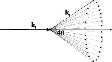
In a powder, there are billions of randomly oriented crystal grains, typically of \(\mu\)m size. Hence, it is safe to assume that all lattice orientations are represented equally and that extinction effects are absent (see the sections on Crystal mosaicity; secondary extinction and Perfect crystals; primary extinction). Bragg scattering of an incoming monochromatic beam will thus happen in all possible ways that fulfill the Bragg law in equation \eqref{eq:bragg}. The resulting scattering will occur on cones of opening angles of \(4\theta\), the Debye-Scherrer cones. This is illustrated in Figure xx--CrossReference--fig:DScone--xx.
To obtain the total scattering cross section from a powder, we average the cross section from equation \eqref{eq:bragg_half_int} over all orientations of a given lattice vector, \({\boldsymbol\tau}\). We use polar coordinates, \((\phi,\omega)\), where \(\omega\) is the angle between \({\bf k}_{\rm i}\) and \(\boldsymbol\tau\) as in Figure xx--CrossReference--fig:scatteringplane--xx and \(\phi\) is the (unimportant) rotation angle around \({\bf k}_{\rm i}\).
\begin{align} \label{eq:powdercros0} \sigma_{\tau} &= \frac{1}{4\pi} \int \sigma_{\boldsymbol\tau} d\Omega = \frac{1}{4\pi} \int \sigma_{\boldsymbol\tau} d\phi \sin(\omega) d\omega\nonumber \\ &= \dfrac{N (2\pi)^3}{V_0} \dfrac{2}{k_{\rm i}} \exp(-2W) \left| F_{\rm N}({\boldsymbol\tau})\right|^2 \dfrac{1}{4\pi} \displaystyle\int 2\pi \sin(\omega) \delta(\tau^2-2k_{\rm i}\tau\cos(\omega)) d\omega \nonumber\\ &= V \exp(-2W) \dfrac{1}{V_0^2} \dfrac{\lambda^3}{4 \sin\theta} j_\tau \left| F_{\rm N}({\boldsymbol\tau}) \right|^2 .\nonumber \end{align}
In the last step, we have included \(j_\tau\), which is the multiplicity of the reflection, meaning the number of crystallographically equivalent lattice planes that all contribute to the scattering. One example is the cubic \((100)\) reflection, with crystallographically equivalent reflections \((010)\), \((001)\), \((\bar{1}00)\), \((0\bar{1}0)\), and \((00\bar{1})\), giving \(j_{100}=6\).
In high-symmetry crystal structures, there may be non-equivalent reflections with the same length of \({\boldsymbol\tau}\). Examples are the cubic \((221)\) and \((300)\) reflections - and the cubic \((333)\) and \((511)\) reflections. In a powder, there is no way to separate these contributions to the scattering. Hence, to reach a description of the scattered intensity at a particular value of \(q\), we must sum over all reflections of same length of \(\tau\), reaching
\begin{equation}\label{eq:powdercross} \sigma_{q} = \displaystyle\sum_{|{\boldsymbol\tau}|=q} \sigma_{ {\boldsymbol\tau}} = V \exp(-2W) \dfrac{1}{V_0^2} \dfrac{\lambda^3}{4 \sin\theta} \displaystyle\sum_{|{\boldsymbol\tau}|=q} j_\tau \left| F_{\rm N}({\boldsymbol\tau}) \right|^2 . \end{equation}
Experimental considerations
A closer look at equation \eqref{eq:powdercross} reveals that the only sample-dependent quantity is the nuclear structure factor, \(F_{\rm N}({\boldsymbol\tau})\). It is thus possible to determine the relative nuclear structure factor for a number of reflections from the relative intensity of the scattered neutrons. This can be used to determine the position of the atoms within the unit cell. The size and shape of the unit cell (the lattice parameters) are, in turn, determined by the position of the reflections, via the Bragg law. A number of standard programs exist to perform this analysis.
Diffraction from nano-sized systems
If the crystal grains are very small, often meaning below 100-500 nm, the "infinite crystal" approximation leading to the Bragg law in equation \eqref{eq:bragg} breaks down. It is then important to reconcile equation \eqref{eq:diffract2} for a nano-sized particle. The resulting mathematics is tedious, but the result is rather simple. The Bragg peaks broaden to a width (FWHM) of approximately
\begin{equation}\label{eq:nano_broad} \Delta q \approx \dfrac{2\pi}{L} , \end{equation}
where \(L\) here is a typical dimension of the particle. We now dig a little deeper into the effect nano-sizes have on the diffraction signal.
A cubic nanoparticle
We first illustrate equation \eqref{eq:nano_broad} with an example. Consider a simple cubic Bravais crystal with lattice constant \(a\). Let also the outer shape of the particle be cubic with side length \(d\). The atoms along a side are numbered from \(0\) to \(m-1\), where \(m=d/a\). The scattering cross section for \({\mathbf q}\) parallel to one side of the cube (here taken as the \(x\)-direction) reads:
\begin{align}\label{eq:diffract_nano} \dfrac{d\sigma}{d\Omega} &= \exp(-2W) \biggr| b m^2 \displaystyle\sum_{n=0}^{m-1} \exp(i q_x n a) \biggr|^2 \\ &= \exp(-2W) m^4 b^2 \left| \dfrac {1-\exp(i q_x m a)}{1-\exp(i q_x a)} \right|^2 \nonumber\\ &= \exp(-2W) m^4 b^2 \left| \dfrac{\sin(m q_x a/2)}{\sin(q_x a/2)} \right|^2 .\nonumber \end{align}
This expression peaks around \(q_x = 2\pi/a\), which is just the Bragg condition. However, the peak has a width of \(\Delta q_x = 2\pi/(ma) = 2\pi/L\) as anticipated above. (The width of the reflection in the \(y\) and \(z\) directions are identical.)
It should be noticed that the squared term in equation \eqref{eq:diffract_nano} has a peak amplitude of \(m^2\), meaning that the total peak amplitude is proportional to \(m^6=N^2\). We should, however, also take into account that the total broadening of the reflection in reciprocal space scales as \(m^{-3}=N^{-1}\). Hence, the integrated intensity of the diffraction peak is proportional to \(N\) - and hence to the particle volume, \(V\) - as was also found in the infinite system, c.f. \eqref{eq:diffract}.
The Scherrer equation
The literature goes one step further into this problem. We will not go into any details with the derivation, but the "apparent" size of the particle is found to be given by the Scherrer equation originally derived for X-ray diffraction[1]:
\begin{equation}\label{dummy2079019572} \epsilon = \dfrac{\lambda}{b \cos(\theta)} , \end{equation}
where \(b\) is the angular broadening of the peak in radians. Identifying \(b = \delta(2\theta) = 2 \delta\theta\), we reach \(\epsilon = \pi / (k \cos(\theta) \delta\theta)\). From the identity \(q=2 k \sin(\theta)\) we reach \(\delta q = 2 k \cos(\theta) \delta \theta\), leading to
\begin{equation}\label{dummy1764686862} \epsilon = \dfrac{2 \pi}{\delta q} , \end{equation}
as we anticipated in equation \eqref{eq:nano_broad}.
The relation between the "true" particle size, \(p = (V)^{1/3}\) and the "apparent" size, \(\epsilon\) is given by
\begin{equation}\label{dummy1773762082} p = K \epsilon , \end{equation}
where \(K\) is a constant of the order unity. This is discussed in great detail for different particle shapes in Ref. [1].
Powder scattering instruments
We will here present typical lay-out of powder scattering instruments for continuous and pulsed sources, respectively.
A powder diffractometer at a continuous source
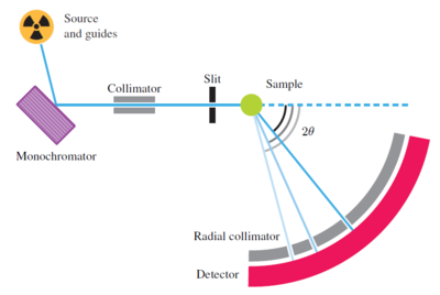
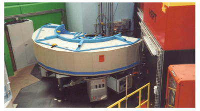
A typical continuous-source powder diffractometer, the HRPT instrument at PSI, is illustrated in Figure xx--CrossReference--fig:HRPT1--xx and Figure xx--CrossReference--fig:HRPT2--xx. The instrument bears much resemblance to the two-axis diffractometer shown in the introduction to this chapter:
- Source: The diffractometer uses a beam of thermal neutrons straight from a beam port without use of neutron guides.
- Monochromator: The beam is diffracted by a monochromator (see Determining the incoming neutron wavelength), which selects the neutron wavelength, typically in the range 1-2~\AA .
- Collimator: The monochromatic beam then passes through a narrow horizontal Soller collimator.
- Sample: The low-divergent, monochromatic beam hits the powder sample, which is often situated in a vacuum environment to reduce background from air scattering. In the sample, the neutrons are scattered according to Bragg's law, see Diffraction from crystals.
- Detector: The scattered neutrons are detected by a large arc-shaped detector bank, with typically hundreds of channels, each covering a narrow range of the scattering angle, \(2\theta\). The detectors have a limited height (perhaps 10-20~cm), to avoid a smearing effect in the data, caused by the blur in total scattering angle when the out-of-plane component is significant.
- Radial collimator: Background neutrons flying around in the sample-detector area are suppressed by a radial collimator between sample and detector. \\
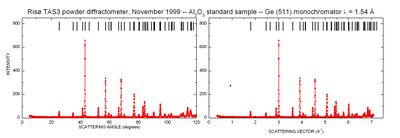
A typical set of powder diffraction data is given in Figure xx--CrossReference--fig:powderdata--xx. Both the raw data and the data converted into scattering vector is shown. The background value between the peaks is mostly elastic incoherent scattering from the sample, but also thermal diffuse scattering contributes at larger scattering angles; see Scattering from lattice vibrations. Towards low scattering angles, there is an increased background due to small-angle scattering of the direct beam.
As can be clearly seen, the resolution of the diffractometer (the width of the powder peaks) varies with scattering angle. In particular, the peaks are broadest at high scattering angles. This effect is well understood, but we will not go into details with it here.
A powder diffractometer at a pulsed source
In a time-of-flight diffraction experiment, the neutron wavelength will change with time, with the shortest wavelength arriving earliest. Hence, at a typical moment in time, there will be Bragg scattering from several lattice spacings. However, the scattering angle from any given reflection will increase with time as the wavelength increases.
To maximize count rate, a typical powder diffractometer is equipped with a large number of time- and position-sensitive detectors that cover a significant fraction of the \(4\pi\) solid angle. The typical raw data from a time-of-flight powder diffraction experiment will be (transformed to be) two-dimensional: Neutron counts vs. flight time, \(t\), and detector angle, \(2\theta\). In such a plot, powder lines will be seen as connected curves through \((2\theta,t)\) space. The processed data will contain only neutron intensity vs. \(q\) (or vs. lattice spacing, \(d\)), probably normalized in proper units of cross section.
The presently most powerful time-of-flight diffractometer is named GEM, and is placed at the 50 Hz source ISIS (UK). With this instrument, a complete powder diffraction pattern can be recorded within a single pulse (lasting 10-15 ms). In this way, it is possible to monitor diffraction signals from fast processes in real time, e.g. chemical reactions.
← Previous page: Neutron reflectivity
→ Exercises: Exercises in Diffraction from crystals
→ Next page: Imaging
