Neutron sources and moderators
This chapter deals with the production and moderation of research-purpose neutrons. The basics of the instrumentation that extracts and utilizes neutrons from these sources are discussed on the Instrumentation page, and the instruments themselves are discussed in almost all the remaining pages of these notes.
Neutron sources
We here describe how neutrons are produced, and where large-scale neutron scattering facilities are located around the world.
Producing neutrons
Neutrons can be produced in a number of ways, e.g. as by-products of cosmic radiation or radioactive decay of heavy nuclei. One often used laboratory neutron source is Californium, \(^{252}\)Cf, which emits neutrons by spontaneous fission (on average 3-4 neutrons per fission[1]). However, the \(^{252}\)Cf half life time of only ~2 years makes frequent source changes necessary. A more long lived laboratory source is the radium-beryllium source. Here, the radium decays spontaneously with a half life of ~1600 years according to
\begin{equation}\label{dummy172353487} {}^{226}{\rm Ra} \rightarrow {}^{222}{\rm Rn} + {}^4\alpha + Q , \end{equation}
with the heat release \(Q = 4.871\) MeV. In the presence of berylium, a neutron is released according to
\begin{equation}\label{dummy1700707666} {}^4\alpha + {}^9{\rm Be} \rightarrow n + {}^{12}{\rm C} . \end{equation}
More recently, neutrons have been produced in a laboratory experiment, using a pyroelectric crystal[2] or a high electrical field [3] to accelerate ions of deuterium (the heavy hydrogen isotope \(^2\)D) to high energies. This will produce neutrons through the reaction
\begin{equation}\label{dummy1166919397} {}^2{\rm D} + {}^2{\rm D} \rightarrow \, ^3{\rm He} + n + Q , \end{equation}
where \(Q\) is an excess energy of 3.27 MeV, of which around 2.5 MeV goes to the neutron.
As mentioned in the Introduction to neutron scattering page, and illustrated in the neutron production figure, neutron sources created for the purpose of materials investigation by scattering are either based upon chain reaction in a nuclear reactor or upon accelerator-driven spallation processes.
In nuclear reactors, neutrons are produced in the fission process
\begin{equation}\label{dummy229023259} {}^{235}{\rm U} + n \rightarrow \, {\rm D}_1 + {\rm D}_2 + \text{2-3}\, n + Q , \end{equation}
where D represent a range of daughter nuclei, and the released enrgy \(Q\) is of the order 200 MeV. A \({}^{235}\)U fission typically yields 1.4 excess neutron per nuclear process[4]. Research reactors with compact cores are used for neutron scattering purposes, rather than the more abundant nuclear power plants that have much larger cores. Reactor sources usually emit a continuous stream of neutrons, except for the remarkable pulsed reactor source in Dubna (RUS), where two large wheels drive the neutron reflectors in a way, so that criticality is reached only in short bursts.
A spallation source is driven by a proton accelerator, which emits protons with energies in the range 1-3 GeV. The protons collide with heavy, neutron-rich nuclei, which are destroyed in the process to many smaller fragments, releasing of the order 10-20 neutrons per proton. Spallation sources are typically pulsed, but can also be pseudo-continuous, as is the case at SINQ at the Paul Scherrer Institute, PSI (CH).
Neutron scattering facilities
A few dozens of neutron sources exist over the world, most of these in Europe, North America, and Asia. During the last decade, the leading sources have been those of ILL (F) and ISIS (UK). Many reactor sources built in the 1960's have exceeded their lifetime and are now closed. Notable close-downs of research reactors have been seen (in chronological order) at Brookhaven (US), Risø (DK), Studsvik (S), Jülich (D), Geestacht (D), and Kjeller (N). Also the spallation source IPNS (US) was recently closed down, and the reactor in Berlin and Paris are scheduled to close by end of 2019.
To compensate for this loss, and to bring progress to neutron scattering science, new advanced neutron sources are being built and commisioned. It is worth mentioning the new reactors FRM-2 at Technical University of Munich (D), OPAL at ANSTO in Sydney (AUS), and CARR at CIAE (China). In addition, major upgrades are being performed at ILL.
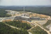
Most important for the future are, however, the spallation sources. The second target station at the ISIS spallation source has almost doubled the number of instruments at this facility. Even more impressive are, however, the new powerful spallation sources SNS, Oak Ridge, Tennessee[5] (first neutrons April 2006; Figure xx--CrossReference--fig:SNS--xx) and J-PARC, Tokai, Japan[6] (first neutrons May 2008; re-opened December 2011 after earthquake/tsunami damage).
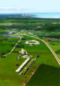
An even more ambitious project, the European Spallation Source (ESS) has been promoted over the last 20 years. In May 2009 it was decided to locate this source in Lund (S), and in July 2014 the construction work was initiated. A sketch of the ESS on the local site in Lund is given in Figure xx--CrossReference--fig:ESS--xx. The ESS project is backed up by 17 European countries, including Germany, UK, and France. According to the present plans, the first neutrons will be produced in late 2019[7].
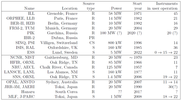
In Table xx--CrossReference--tab:sources--xx, we list the most important present neutron sources. European sources not listed include the smaller reactors in Delft (NL), Budapest (H), Rez (CZ), and Kjeller (N). A continuously updated list of neutron sources worldwide is found at collaborative home pages [8][9].
The future may see even other types of sources, the so-called compact neutron sources, which are accelerator driven, but somewhat smaller than the large spallation sources present today. It is under discussion to build such sources in a number of countries, for example France and Germany. These sources could play the same role in the neutron science landscape as the low-to-medium power national sources have done during the 20th century.
Access to neutron sources
Research centers for neutron scattering are typically nationally funded facilities; except ILL and ESS that are European. The most common way of utilizing these facilities is when research groups propose scientific projects to be performed at particular instruments on the facility. These proposals are then considered by an independent expert panel, which will advice the facility directors on the quality and scientific urgency of proposals, leading to a selection of successful proposals.
Most facilities have deadline for proposals twice per year, and access (or beam time) is often allocated 3-4 months after the deadline for the half-year period starting 2-3 months later. Hence, the actual experiment is typically performed 6-12 months after the proposal submission. However, most facilities have other ways of allocating beam time for particularly urgent experiments.
- ↑ W.W.T Crane, G.H. Higgins, and S.G. Thompson. Phys. Rev., vol. 97, p. 242 (1955)
- ↑ B. Naranjo and J.K. Gimzewski and S. Putterman, Nature, vol. 434, p. 1115 (2005)
- ↑ See the home page http://www.aip.org/tip/INPHFA/vol-9/iss-6/p22.html
- ↑ J. Duderstadt and L. Hamilton, Nuclear Resactor Analysis (Wiley, 1976)
- ↑ See http://www.sns.gov
- ↑ See http://j-parc.jp/MatLife/en/index.html
- ↑ See http://www.ess-scandinavia.eu
- ↑ See the home page of the NMI3 project http://www.neutron-eu.net
- ↑ See the neutron facility collaboration home page at http://www.neutronsources.org/
Moderators
Neutrons produced in nuclear reactions typically have energies in the MeV regime. To be useful in materials research, the neutrons must have their energies reduced by many orders of magnitude.
We here describe the basics of this problem. For more information, a good introduction to neutron moderator physics is found in Ref. [1].
The moderation process
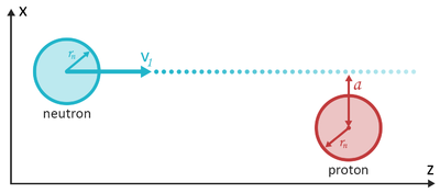
The neutron moderation is performed by a large number of successive collisions with a material that scatters strongly, but absorbs weakly. Here, hydrogen (H) is an almost perfect choice, also since its nuclear mass is similar to that of the neutron. This enables the H nucleus to absorb a large fraction of the neutron energy in each collision.
To show this, in a classical mechanics description, let us for simplicity consider the neutron and the protons as spherical particles with identical mass, \(m_{\rm n}\), and with identical radii, \(r_{\rm n}\). In the collision, we consider the proton to be at rest, and the neutron to move with the velocity \(v_1\) along the \(z\)-axis, and hence with a kinetic energy of \(E_1 = m_{\rm n} v_1^2 / 2\). The closest distance from the neutron trajectory to the proton center is denoted the impact parameter, \(a\), as seen in Figure xx--CrossReference--fig:moderation--xx. We consider the neutron to have a random trajectory, hence the probability for having a particular impact parameter, \(a\), is proportional to \(a\). If \(a<2r_{\rm n}\), a collision takes place.
We now define the \((x,z)\) plane to contain both the proton position and the neutron trajectory. After the scattering, the proton will remain in the plane, moving with the velocity \({\bf v}_{2,p}\). The proton trajectory makes an angle to the \(z\)-axis of
\begin{equation}\label{eq:moderator_angle} \sin\phi = \dfrac{a}{2r_{\rm n}}. \, \end{equation}
We denote the neutron velocity after the scattering by \({\bf v}_{2,n}\).
Now, energy conservation and momentum conservation in the \((x,z)\) plane gives three equations
\begin{align} m_{\rm n} v_1^2 &= m_{\rm n} (v_{2,p}^2 + v_{2,n}^2) \label{dummy1931789634}\\ m_{\rm n} v_1 &= m_{\rm n} (v^z_{2,p} + v^z_{2,n}) \label{dummy1425646361}\\ 0 &= m_{\rm n} (v^x_{2,p} + v^x_{2,n}) \label{dummy1897979680} \end{align}
and equation \eqref{eq:moderator_angle} give the fourth equation to determine the four unknowns components of \({\bf v}_{2,n}\) and \({\bf v}_{2,p}\). The solution for the velocity of the proton after the collision is
\begin{equation}\label{dummy870671655} v_{2,p} = v_1 \cos\phi . \, \end{equation}
The probability of reaching an impact parameter of \(a\) is proportional to \(a\) up to a value of \(2r_{\rm n}\). From this, we can calculate the average energy taken up by the proton in the collision. The result is
\begin{equation}\label{eq:E_half} E_{2,p} = \dfrac{E_1}{ 2} . \, \end{equation}
The proof of this is left to the reader, and is posed as the problem Hydrogen as a moderator.
A more detailed model will also provide the result that the neutron loses on average half of its energy per collision. Slowing the neutron energy by (a typical value of) 8 orders of magnitude, thus takes "only" 25-30 collisions. This is clearly within practical limits, since the typical mean free path in a hydrogen-rich material is of the order a few mm.
When the neutron energy becomes comparable to the (thermal) energy of the protons, the approximation of zero proton velocity breaks down, and a much more complex description is necessary, including the thermal motion of the proton and its surroundings. The effect is, nevertheless, that the neutrons quickly reach thermal equilibrium with the surrounding material.
Energy distribution of moderated neutrons
Most moderators consist of a tank with liquid water (H\(_2\)O; 300 K), which will slow down neutrons to roughly thermal equilibrium. When neutrons of lower energies are required, moderators of liquid hydrogen (H\(_2\); 30 K) or solid methane (CH\(_4\); 100 K) are used in connection with water pre-moderators. At ILL, there is even a hot moderator consisting of graphite at 2000 K. We will here discuss the implications of the moderator temperature.
Neutrons moderated at a temperature, \(T\), will ideally have a distribution of velocities, \(v\), given by the Maxwellian distribution of velocities, which is proportional to \(v^2\) times the Boltzmann factor \(\exp(-E_{\rm kin}/k_{\rm B}T)\). Since neutron emission through a (imaginary) hole at the moderator surface is essentially an effusion process, the intensity of neutrons from a beam port can be written as:
\begin{equation}\label{eq:maxwell_v} I(v) = I_0 v^{3} \exp\left(- \dfrac{m_{\rm n} v^2}{2 k_{\rm B} T}\right) , \end{equation}
where \(I_0\) is a constant proportional to the source power, \(k_{\rm B}\) is Bolzmann's constant, and the extra power of \(v\) comes from the effusion (faster particles have higher probability per time of leaving through the hole). The velocity distribution \eqref{eq:maxwell_v} peaks at \(v_{\rm max} = \sqrt{3 k_{\rm B}T/m_{\rm n}}\), corresponding to an energy of \(3 k_{\rm B} T / 2\).
It is customary to define the equivalent temperature of neutrons with a certain energy. The relation is given by
\begin{equation}\label{dummy1240073730} E = \dfrac{m_{\rm n} v^2}{2} = k_{\rm B} T_{\rm equiv} . \end{equation}
Describing the Maxwellian distribution in equation \eqref{eq:maxwell_v} in terms of wavelength requires some care. Since \(v = 2 \pi \hbar / (m_{\rm n} \lambda)\), we have \(dv = - 2 \pi \hbar d\lambda / (m_{\rm n} \lambda^2)\). Hence, the wavelength and velocity axes do not scale linearly, and a transformation of the distribution must be applied:
\begin{equation}\label{eq:maxwell_l} I(\lambda) \equiv \dfrac{dN}{d\lambda} = \dfrac{dN}{dv} \left| \dfrac{dv}{d\lambda}\right| = I'_0 \lambda^{-5} \exp\left(- \dfrac{2 \pi^2 \hbar^2}{\lambda^2 m_{\rm n} k_{\rm B} T}\right) , \end{equation}
where \(I_0' \propto I_0\) and \(N\) is the total number of neutrons. This distribution peaks at \(\lambda = 2 \pi \hbar \sqrt{3 / (5 m_{\rm n} k_{\rm B} T)}\), corresponding to \(E = 5 k_{\rm B} T / 3\). The energy equivalent of the peak value is thus changed by 10% between the two representations of the Maxwellian distribution due to the non-linear transformation, even though the two equations describe the same neutrons. Neutron moderator spectra are typically expressed in terms of the wavelength distribution, as illustrated in Figure xx--CrossReference--fig:maxwell--xx.
Moderator brilliance and the Liouville theorem
Since neutron scattering is mostly an intensity limited technique, an important quantity for a neutron source (a moderator) is the produced number of neutrons per unit of time. However, an even more useful number is the moderator brilliance, \(B\), which describes the produced number of neutrons per unit of time, per moderator area, per solid angle of flight direction, per wavelength interval. For example, a compact reactor core will have a higher brilliance than a less dense one, even though the total neutron production may be equal. In reality, the brilliance (or peak brilliance for pulsed sources) is almost the only relevant value for a neutron source. Brilliance is useful also at other positions in the neutron instrument, typically at the sample position, and has the same definition as above. In general \(B\) depends upon the position of the moderator, the time (for pulsed sources), and the direction and wavelength of the emitted neutrons
\begin{equation}\label{dummy1171737310} B=B(t,{\mathbf r},\hat{\mathbf v},\lambda) . \end{equation}
In terms of statistical mechanics, the brilliance is closely connected with phase space density, \(\phi({\bf r},{\bf v})\). This can be seen from the observation that \(\lambda\) can be written in terms of \(v\), and the position perpendicular to the main beam direction is given as \(z=vt\).
For an ensemble of particles undergoing only passive processes, the very powerful Liouville theorem is valid. It states that the phase space density cannot increase[2]. In the context of a neutron scattering instrument, this means that the brilliance at the neutron beam can under no circumstances be larger than that of the (brightest spot at the) moderator[3]. As a relevant example of this, focusing mirrors or lenses are somtimes used to bring more neutrons on to a small sample. According to the Liouville theorem, however, the increase in number of neutrons will come from an increase in the spread of their velocity directions (their divergence).
Real moderators
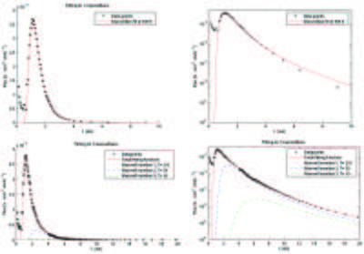
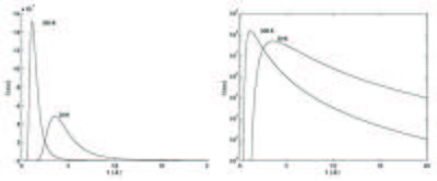
To improve transmission, real moderators have a limited thickness and hence do not moderate the neutrons completely. Their velocity distribution should rather be described by the sum of two or (most often) three Maxwellians, possibly with the addition of a tail towards high energies/low wavelengths, describing neutrons that are scattered only few times in the moderator. This is illustrated for the SINQ source at PSI in Figure xx--CrossReference--fig:SINQmoderators--xx. To avoid completely unmoderated neutrons from the source, the moderator geometry is chosen so that there is no line-of-sight between the place of neutron production and the beam port that opens out to the neutron scattering instruments.
Recent developments have shown that inhomogeneities in the moderator geometry, like holes and grooves, can locally enhance the neutron brilliance by up to a factor two, since these will generate a direct view to the moderator center, where the neutron density is larger[4]. However, design and detailed understanding of moderator systems is complex and is performed with the use of heavy nuclear physics simulations using codes like MCNPX and GEANT-4[5][6]. A description of this is beyond the scope of these notes. In the following, we will be satisfied with the existence of thermal and cold neutrons sources, and we will concentrate on the utilization of moderated neutrons.
- ↑ G.S. Bauer, Neutron Sources - Lecture Notes of the Introductory Course to the ECNS99, p. 12-26, (Report KFKI-1999-04/E)
- ↑ L.D. Landau and E.M. Lifshitz, Course in Theoretical Physics, vol. 5 Statistical Physics (Butterworth-Heinemann, 1951)
- ↑ K.H. Klenø, Exploration of the challenges of neutrons optics and instrumentation at long-pulsed spallation sources, Ph.D. thesis, Niels Bohr Institute, University of Copenhagen 2013 (submitted)
- ↑ D.J. Picton, S.M. Bennington, T.A. Broome, T.D. Benyon, Nucl. Instr. Meth. A 545, 363 (2005)
- ↑ E. Padovani, S.A. Pozzi, S.D. Clarke, E.C. Miller, MCNPX-PoliMi User's Manual, C00791 MNYCP, Radiation Safety Information Computational Center, Oak Ridge National Laboratory, 2012
- ↑ Geant 4.9.5 Physics Reference Manual, http://geant4.web.cern.ch/geant4/UserDocumentation/UsersGuides/PhysicsReferenceManual/BackupVersions/V9.5/fo/PhysicsReferenceManual.pdf, December 2012
← Previous page: Basics of neutron scattering
→ Exercises: Exercises in Neutron sources and moderators
→ Next page: Instrumentation
