Neutron reflectivity
Author: Andrew Wildes, Institut Laue-Langevin
Reflectometry probes the properties of thin films and their interfaces, even if they are buried within a sample. The technique is non-destructive and it is straight-forward to present the measurements in absolute, dimensionless units.
The technique consists of measuring the reflected intensity of a beam from a flat sample as a function of the momentum transfer given by the beam to the sample. Reflectometry probes the refractive index, which is a quantity used to describe the propagation of waves in a medium relative to the propagation of waves in a vacuum. The refractive index can change significantly from medium to medium, and thus reflectometry determines the refractive index as a function of depth in the sample. The rate at which the refractive index changes as a function of depth will also depend on the quality and smoothness of the interfaces between media, and interface effects are also probed with reflectometry. As a result, reflectometry measurements with neutrons (and X-rays) are extremely important in the study of thin films and stratified media.
Thin films and interfaces
The definition of a "thin film" is certainly ambiguous. However in current scientific discussion "thin" refers to nanometer-sized length scales. Films with thicknesses of this order of magnitude are extremely important. In biology, examples include membranes and cell walls. In chemistry, examples include surfactants and catalysts. In physics there is a great deal of interest in low-dimensional magnetism and confinement effects. In addition, films and multilayers of these thicknesses are extensively used for information technology.
In all these scientific fields, it is important to determine what occurs at the interfaces on the properties of the film, and the influence of having a severe spatial constraint on the physical properties of the film. A thin film of a material is highly unlikely to have the same properties of the same material in bulk, and the morphology of an interface can significantly change any interactions that can occur between two materials. Films can also be stacked to produce stratified layers, giving global properties to the material that are very different to the properties of the individual constituents.
The refractive index
The refractive index of a medium is a concept that is heavily used in optics. It relates to the fact that the traveling speed of a wave can vary when it travels through a medium.
The refractive index of the material, \(n_{\rm m}\), is defined by
\begin{equation} n_{\rm m}=\frac{\lambda_0}{\lambda_{\rm m}}=\frac{k_{\rm m}}{k_0}, \label{reflectivityeq:n} \end{equation}
where \(\lambda_0\) is the wavelength in the vacuum, \(\lambda_{\rm m}\) is the wavelength in the medium, and likewise for the wavenumbers.
*Quantum mechanical derivation
The refractive index may be derived by solving a wave equation with the kinetic and potential energies for the wave in the medium. Neutron motion can be described by waves using quantum mechanics, and the relevant wave equation to describe their motion is given by:
\begin{equation} \frac{\hbar^2}{2m_{\rm n}}\frac{d^2\psi}{dr^2}+\left(E-\overline{V}\right)\psi=0, \label{reflectivityeq:WaveEqn} \end{equation}
where \(E\) is the total neutron energy.
The quantity \(\overline{V}\) is the spatial average of the neutron potential, \(V\left(\bf{r}\right)\). A neutron propagating in a medium will see the average scattering length of all the nuclei in the medium,
\begin{equation} \overline{V}=\frac{1}{\text{volume}}\int V\left({\bf{r}}\right)d{\bf{r}}. \label{eq:Vrho} \end{equation}
This quantity is insensitive to the atomistic structure of the medium, hence the refractive index will be the same irrespective of whether the medium is liquid, amorphous, polycrystalline of monocrystalline. This is very different to the topic of neutron diffraction, which measures the arangement of the individual atoms (crystal structure).
Equation \eqref{eq:Vrho} can be shown to rigorously hold, and the proof can be summarized by interpreting the solution of \eqref{reflectivityeq:WaveEqn} as diffraction in the limit \(q = 0\). The length scales probed by a diffraction experiment are proportional to \(q^{-1}\). As \(q \rightarrow 0\), the length scale thus becomes much larger than the distances between atoms. In the limit \(q = 0\), all atoms scatter coherently, and thus \eqref{eq:Vrho} is valid. Equation \eqref{reflectivityeq:WaveEqn} may be rewritten in terms of its wavenumber, \(k\),
\begin{equation} \frac{d^2\psi}{dr^2}+k^2\psi=0, \label{reflectivityeq:WaveEqnk} \end{equation}
where
\begin{equation} k^2=\frac{2m}{\hbar^2}\left(E-\overline{V}\right). \label{eq:k2} \end{equation}
The mean potential for the neutron in a vacuum is equal to zero, \(\overline{V}=0\). The total energy, \(E\), must always be conserved and is therefore always equal to the kinetic energy of the neutron when it travels in a vacuum,
\begin{equation} E=\frac{\hbar^2k_0^2}{2m}, \label{reflectivityeq:E} \end{equation}
and thus the refractive index may be written
\begin{equation} n^2=1-\frac{\overline{V}}{E}. \label{reflectivityeq:n2} \end{equation}
Index of refraction from materials
In the absence of magnetism, the potential for the interaction of a neutron with a nucleus is given by the Fermi pseudo-potential
\begin{equation} V_j({\bf r})=\frac{2\pi\hbar^2}{m_{\rm n}}b_j\delta\left({\bf r}-{\bf r}_j\right). \label{reflectivityeq:Vr} \end{equation}
Integrating equation \eqref{reflectivityeq:Vr} over the volume of the medium gives
\begin{equation} \overline{V}=\frac{1}{\text{volume}}\int V_N\left({\bf{r}}\right)d{\bf{r}}= \frac{2\pi\hbar^2}{m}\rho\overline{b}, \label{reflectivityeq:Vrhob} \end{equation}
where \(\rho\) is the atomic number density and \(\overline{b}\) is the average scattering length of all the nuclei in the medium. The refractive index is therefore sensitive to \(\rho\overline{b}\), the average scattering length density, and is given by
\begin{equation} n^2=1-\frac{4\pi \rho\overline{b}}{k_0^2}=1-\frac{\lambda_0^2}{\pi}\rho\overline{b} \label{reflectivityeq:n2rhob} \end{equation}
The nuclear scattering length is a complex quantity and may be written \(\bar{b} = \bar{b}' - i \bar{b}'' \). The real part is related to t he bound coherent scattering length, \(\bar{b}_c\), and to incoherent scattering due to the interaction between the spin of the neutron and any spin on the nuclei. The imaginary part is given by the average absorption cross-section, \(\bar{\sigma}_a\), through the relation
\begin{equation} \bar{b}'' = \frac{ k \bar{\sigma}_a }{4 \pi} = \frac{\bar{\sigma}_a}{2 \lambda} . \end{equation}
The refractive index is sometimes Taylor expanded and written
\begin{equation} n \approx 1- \frac{\lambda_0^2}{2\pi}\rho\overline{b}_c. \label{reflectivityeq:nTaylor} \end{equation}
It may be noted that equations \eqref{reflectivityeq:n} to \eqref{reflectivityeq:n2} also hold for X-rays, and that the final expression for the X-ray refractive index is very similar equation \eqref{reflectivityeq:n2rhob} with the difference that the scattering length density, \(\rho\overline{b}_c\) for X-rays is given by the electron density multiplied by the classical electron radius, \(\rho_e r_0\). The absorption cross-sections for X-rays is also much larger than those for neutrons and must always be included in the final expression for the refractive index.
Reflection from a smooth, flat interface
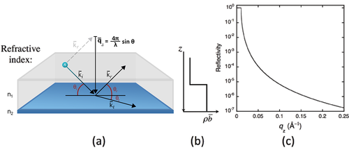
The potential for a wave changes at an interface between two media with different refractive indices. Through conservation of energy and momentum, the wave front at the interface splits in to a reflected part and a transmitted, or refracted, part. A schematic showing the effect is given in Figure xx--CrossReference--reflectivityfig:singleint--xx(a).
The incident wave is described by the wavevector \({\bf{k}}_i\) and subtends an angle \(\theta_i\) with the interface. Part of the wave is reflected at the interface to give a reflected wave vector, \({\bf{k}}_r\), with a subtended angle, \(\theta_r\). In the case of a perfectly flat interface the reflected angle equals the incident angle, \(\theta_i = \theta_r\), and the momentum transfer to the wave is normal to the interface, hereafter defined as the \(z\) direction. This is known as specular scattering.
The solution to the wave equations describing the reflected and transmitted waves depends on only one spatial direction, and this is the \(z\) direction. An exact algebraic solution is known, and it comes from matching the amplitudes and phases of the incident, reflected, and transmitted waves at the interface. Because the equations are one-dimensional, articles often show the refractive index, and more specifically the scattering length density, \(\rho\overline{b}\), as a function of the depth, \(z\), in the sample. These plots show the neutron potential, \(\overline{V}\). An example for a single interface is shown in Figure xx--CrossReference--reflectivityfig:singleint--xx(b).
Part of the wavefront may be transmitted with angle \(\theta_t\) to give a refracted wavevector, \({\bf{k}}_t\). The wavelengths and angles in the two media are related through Snell's Law
\begin{equation} n_1 \cos \theta_1 = n_2 \cos \theta_2. \label{reflectivityeq:Snell} \end{equation}
In the schematic shown in Figure xx--CrossReference--reflectivityfig:singleint--xx, \(\theta_1 = \theta_i\) and \(\theta_2 = \theta_t\).
The amplitudes of the two waves are given by the Fresnel formulae from classical optics theory. These give a reflectivity coefficient, \(r\), and transmission coefficient, \(t\), via the formulas
\begin{equation} r=\frac{n_1\sin\theta_1 - n_2\sin\theta_2}{n_1\sin\theta_1 + n_2\sin\theta_2}=\frac{k_{1z}-k_{2z}}{k_{1z}+k_{2z}}, \label{reflectivityeq:Fr} \end{equation} \begin{equation} t=\frac{2n_1\sin\theta_1}{n_1\sin\theta_1 + n_2\sin\theta_2} = \frac{2k_{1z}}{k_{1z}+k_{2z}}, \label{reflectivityeq:Ft} \end{equation}
where \(k_{jz} = k_j\sin{\theta_j}\) is the component of the wavevector, \({\bf{k}}_j\), along the direction normal to the interface, \(z\). The reflectivity, \(\cal R\), is defined as the reflected intensity, \(I_r\), divided by the incident intensity, \(I_0\). It is an absolute, unitless quantity which can be measured experimentally in a relatively straightforward manner. It is related to the Fresnel reflectivity coefficient through the equation
\begin{equation} {\cal{R}}\left(q_z\right) = \frac{I_r\left(q_z\right)}{I_0} = \left|r\right|^2. \label{reflectivityeq:R} \end{equation}
The reflectivity is a function of the momentum components of the incident and refracted waves normal to the interface, and is here expressed as a function of the momentum transfer of the reflected wave, \(q_z\). This momentum transfer is also normal to the interface and is equal to
\begin{equation} q_z=\frac{4\pi}{\lambda_i}\sin\theta_i . \label{reflectivityeq:qz} \end{equation}
The calculated reflectivity of a neutron beam at the interface between air and a block of silicon is shown in Figure xx--CrossReference--reflectivityfig:singleint--xx(c). It shows a remarkable feature at small \(q_z\) and has a characteristic behaviour at large \(q_z\) that warrant closer inspection.
Total reflection
If \(n_1 > n_2\), equation \eqref{reflectivityeq:Snell} shows that \(\theta_2\) can only be a real number for \(n_2 \ge n_1\cos\theta_1\). Beyond this limit the Fresnel reflection coefficient becomes imaginary and the reflectivity \({\cal{R}} = 1\). This commonly occurs for neutrons as equation \eqref{reflectivityeq:nTaylor} shows that the refractive index of a material with \(\overline{b}_c > 0\) is less than one, and is therefore less than the refractive index for a vacuum. All the neutrons below a critical \(q_z\) will therefore be reflected.
The critical edge below which total reflection is observed is given by
\begin{equation} q_c=\sqrt{16\pi\left(\rho_2\overline{b}_2-\rho_1\overline{b}_1\right)}. \label{reflectivityeq:Critqc} \end{equation}
Equation \eqref{reflectivityeq:Critqc} often expressed as a critical angle
\begin{equation} \theta_c=\lambda_1\sqrt{\frac{\rho_2\overline{b}_2-\rho_1\overline{b}_1}{\pi}}=\frac{\sqrt{4\pi\left(\rho_2\overline{b}_2-\rho_1\overline{b}_1\right)}}{k_1}. \label{reflectivityeq:CritAng} \end{equation}
Equations \eqref{reflectivityeq:Critqc} and \eqref{reflectivityeq:CritAng} are generic, and they become simpler when one of the media is air or vacuum for which \(\rho\overline{b} = 0\).
Reflection far from \(q_c\)
The approximation
\begin{equation} k_{1z}+k_{2z}\approx q_z \label{reflectivityeq:qzapprox} \end{equation}
is valid for \(q_z >> q_c\). Rewriting the reflectivity coefficient as
\begin{equation} r=\frac{k^2_{1z}-k^2_{2z}}{\left(k_{1z}+k_{2z}\right)^2}=\frac{q^2_c}{4\left(k_{1z}+k_{2z}\right)^2} \label{reflectivityeq:rq4} \end{equation}
leads to the observation that the reflectivity for large \(q_z\) will follow the relation
\begin{equation} {\cal{R}}\left(q_z\right) \propto q^{-4}_z. \label{reflectivityeq:Reflq4} \end{equation}
This expression is known as the Porod Law[1][2]. It also holds for reflection from interfaces that do not have total reflection. We also saw this as the large \(q\) limit of the small angle scattering cross section in the previous chapter. At these values of \(q\) the beam is scattering from the interfaces between the liquid used as the solute and the objects suspended in the solute. In effect, these data represent the reflectivity from spherically averaged single interfaces.
Reflectivity as a scattering phenomenon
When describing reflectivity in terms of the sum of scattering from nuclei, the cross-section is given by the square of the Fourier transform of the function used to describe the object that scatters the neutrons. In the case of reflectivity, the function describes the refractive index as a function of depth. An example for a single interface is given in Figure xx--CrossReference--reflectivityfig:singleint--xx(b).
The Fourier transform of this function is proportional to \(q^{-1}_z\). Squaring this function, and accounting for the surface area of the sample, gives the result that the cross-section is proportional to \(q^{-4}_z\), which is the Porod Law. The first Born approximation can therefore be used to calculate reflectivity far from \(q_c\).
However, a principal assumption of this formalism, known as the first Born approximation, is that the scattering must be weak. This is certainly not true as \(q_z \rightarrow 0\). Even in samples without a critical edge, \({\cal{R}}\left(0\right) = 1\). The scattering at small \(q_z\) is always strong, and the first Born approximation fails in this regime. It does not predict total reflection or the presence of a critical edge, and gives \({\cal{R}}\left(0\right) \rightarrow \infty\).
Reflectivity of stratified media
Materials with numerous thin film overlayers are known as stratified media. These materials have numerous interfaces. Reflectivity methods are very useful for characterizing the sharpness of the interfaces and the scattering length densities, which give rise to the refractive index of the layers.
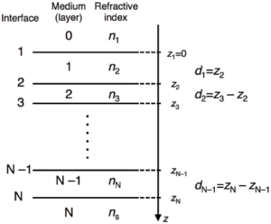
Calculating the reflectivity from stratified layers usually involve numbering the layers from the top of the sample to the bottom in the manner shown in Figure xx--CrossReference--reflectivityfig:multint--xx.
Equations \eqref{reflectivityeq:Fr} and \eqref{reflectivityeq:Ft} may be adapted to give the Fresnel reflection and transmission coefficients at an interface between layers \(j\) and \(j+1\), however this is insufficient to calculate the reflectivity. In addition to the reflected wave, the refracted wave, and the incident wave from above the interface horizon that were all described in the Reflection from a smooth, flat interface section, a second incident wave from below the interface horizon must also be considered. This second incident wave is the reflected wave from interfaces deeper in the sample. The only interface where the second incident wave does not need to be considered is the deepest. Beyond this interface the sample is assumed to be infinitely thick.
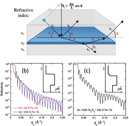
Figure xx--CrossReference--reflectivityfig:twointerfaceint--xx(a) shows a schematic example of the waves that must be considered when calculating the reflectivity from a single film on a substrate. The four waves that must be accounted for at the top interface between the refractive indices \(n_1\) and \(n_2\) are shown. The phase and the amplitude of the reflected wave from the bottom interface will be modified by the path length through the film and hence depends on the thickness, \(d\), of the film. The amplitude of the wave is thus modified by the factor
\begin{equation} a_j = \exp\left(-2ik_{jz}d_j\right). \label{reflectivityeq:Amp2} \end{equation}
The value of \(k_{jz}\) can be expressed as a function of the wavenumber in the topmost layer,
\begin{equation} k_{jz}=k_j\sqrt{\left(1-\cos^2\theta_j\right)}=k_1\sqrt{\left(\frac{n^2_j}{n^2_1}-\cos^2\theta_1\right)}. \label{reflectivityeq:krel} \end{equation}

The reflections from the different interfaces will interfere to give beats in the reflectivity. These beats are also known as `Keissig' fringes. Figure xx--CrossReference--reflectivityfig:twointerfaceint--xx(b) shows calculated examples of the reflectivity from a thin film of iron on silicon. The spacing between these fringes is approximately equal to \(2\pi\) divided by the thickness of the film. This approximation becomes much better far from the critical edge. Nevertheless, the figure shows that the 500 Å film, being ten times thicker than the 50 Å film, always has 10 minima in the Keissig fringes for every one of the thinner film.
Further overlayers lead to further interference, and the final reflectivity comes from a coherent summation of the reflected and transmitted waves at every interface. Separate thicknesses cannot be explicitly determined just by looking at the data, however if the thicknesses of the layers and their refractive indices are sufficiently different (i.e. the contrast between the layers is sufficiently large) then some information can be inferred. Figure xx--CrossReference--reflectivityfig:twointerfaceint--xx(c) shows a calculation for a thin oxide layer on a thicker iron layer. There are clearly two sets of beats present in the Keissig fringes and, from these, the thicknesses of the two layers can be inferred.
It is necessary to perform the complete summation in order to quantitatively analyse reflectivity data. There are two common methods of performing this calculation. The methods are mathematically identical.
The recursive method
This method is described by Parratt[1]. The layers of the sample are numbered as in Figure xx--CrossReference--reflectivityfig:multint--xx, and the Fresnel reflection coefficients for each interface, \(j\), are calculated after modifying equation \eqref{reflectivityeq:Fr} for reflection between layers \(j-1\) and \(j\),
\begin{equation} r_{j-1,j}=\frac{k_{\left(j-1\right)z}-k_{jz}}{k_{\left(j-1\right)z}+k_{jz}}. \label{reflectivityeq:ParrattrN} \end{equation}
The reflection from the \(N\)th interface is given by this Fresnel coefficient multiplied by the appropriate amplitude factor (equation \eqref{reflectivityeq:Amp2})
\begin{equation} R_{N-1,N}=a_{N-1}r_{N-1,N} . \label{reflectivityeq:ParrattRN} \end{equation}
This reflected wave is included in the calculation from the \(j=\left(N-1\right)\)th interface using a recursion formula
\begin{equation} R_{j-1,j}=a^2_{j-1}\left(\frac{R_{j,j+1}+r_{j-1,j}}{R_{j,j+1}r_{j-1,j}+1}\right). \label{reflectivityeq:ParrattrRj} \end{equation}
This recursion is continued to the first interface, noting that \(a_0 = 1\), and the sample reflectivity is given by
\begin{equation} {\cal{R}}=\left|R_{0,1}\right|^2. \label{reflectivityeq:ParrattRef} \end{equation}
The characteristic matrix method
This method is described by Born and Wolf[2] from the work of Abelès[3]. A matrix is written for each of the layers \(j=1...N-1\) in Figure xx--CrossReference--reflectivityfig:multint--xx, and has the form
\begin{equation} {\bf{M}}_j=\left[ \begin{array}{cc} \cos\left(k_{jz}d_j\right) & -\frac{i}{p_j}\sin\left(k_{jz}d_j\right) \\ -ip_j\sin\left(k_{jz}d_j\right) & \cos\left(k_{jz}d_j\right) \end{array} \right], \label{reflectivityeq:Mj} \end{equation}
with the definition that \(p_j=n_j\sin\theta_j\). Note that this can be expressed as a function of the wavenumber and angle at the topmost layer in a similar manner to \(k_jz\) in equation \eqref{reflectivityeq:krel}.
The matrices are then multiplied to give a final \(2 \times 2\) matrix,
\begin{equation} {\bf{M}}_{\cal{R}}={\bf{M}}_1{\bf{M}}_2...{\bf{M}}_{N-1}=\left[ \begin{array}{cc} M_{11} & M_{12} \\ M_{21} & M_{22} \end{array} \right]. \label{reflectivityeq:MR} \end{equation}
The resulting reflectivity coefficient is given by
\begin{equation} r=\frac {\left(M_{11}+M_{12}p_N\right)p_1-\left(M_{21}+M_{22}p_N\right)} {\left(M_{11}+M_{12}p_N\right)p_1+\left(M_{21}+M_{22}p_N\right)}. \label{reflectivityeq:rMat} \end{equation}
The matrix may also be expressed in terms of the Fresnel coefficients in equation \eqref{reflectivityeq:ParrattrN},
\begin{equation} {\bf{C}}_j=\left[ \begin{array}{cc} \exp{ik_{jz}d_j} & r_{j,j+1}\exp{ik_{jz}d_j} \\ r_{j,j+1}\exp{-ik_{jz}d_j} & \exp{-ik_{jz}d_j} \end{array} \right]. \label{reflectivityeq:Cj} \end{equation}
The matrices are then multiplied,
\begin{equation} {\bf{C}}_{\cal{R}}={\bf{C}}_1{\bf{C}}_2...{\bf{C}}_{N-1}=\left[ \begin{array}{cc} C_{11} & C_{12} \\ C_{21} & C_{22} \end{array} \right], \label{reflectivityeq:CR} \end{equation}
and the reflectivity coefficient is given by
\begin{equation} r=\frac{C_{21}}{C_{11}}. \label{reflectivityeq:rMatC} \end{equation}
In both cases the reflectivity \(\cal{R}\), is calculated from the reflectivity coefficient, \(r\), using equation \eqref{reflectivityeq:R}.
The relative merits of the two methods
Mathematically, the two methods are identical. The choice of which to use is essentially a question of which is the more efficiently written as computer code. Matrices, trigonometry, and the algebra of complex numbers are often complicated to code and slower to run when using low level computer languages, hence the recursive method is probably faster and easier to code. High level languages often have matrix algebra and complex numbers included in a software package, hence it may be easier to code reflectivity calculations when using the characteristic matrix method.
Reflectivity of periodically stratified media
Periodically stratified media represent an important category of thin multilayer materials as certain physical aspects, for example optical or electronic properties, can be enhanced or suppressed depending on their structure. This behaviour can be exploited in technology, or in reflectivity experiments when the contribution from certain structural components in the sample can be increased.
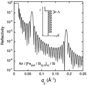
An example of the scattering length density of a periodically stratified sample is shown in Figure xx--CrossReference--reflectivityfig:SL--xx. The sample is formed of ten bilayers, each bilayer consisting of 50 Å Fe and 50 Å Si. The total thickness of the bilayer is therefore \(\Lambda = 100\) Å.
The figure also shows the calculated reflectivity from the sample. Kiessig fringes are clearly visible with a spacing that corresponds roughly to the total thickness of the film. The reflectivity also shows peaks at multiples of \(q_z \approx 2\pi/\Lambda\). These peaks are analogous to Bragg peaks, given by the periodicity of the layers in the sample. They are quite broad in \(q_z\) in the example, but become sharper as more bilayers are added. These peaks are usually quite far from \(q_c\) and can often be analysed using the first Born approximation. It must be noted that reflectivity is not sensitive to the atomic structure of the layers, and that these peaks will appear whether the layers are amorphous or monocrystalline. However, analysis of these peaks can give sensitive information about the structure of an individual period in the sample, in much the same way as the analysis of Bragg peaks from single crystals can be used to determine atomic positions in a diffraction experiment.
In the example, the thicknesses of the two components of the bilayer are equivalent. This results in the even harmonics of the Bragg peaks to be suppressed, i.e. the Bragg peaks appear at \(q_z \approx 2\pi M/\Lambda\), where \(M = 1, 3, 5, ...\). If the thicknesses are not equivalent, the even harmonics will begin to appear. Reflectivity measurements at these positions are therefore very sensitive to the structural quality of the sample.
It may be noted that the reflectivity of the first harmonic is quite large. This has been exploited in modern neutron optics. If many bilayers are deposited such that \(\Lambda\) is slowly varied as a function of depth, the reflectivity will show many such intense Bragg peaks with slightly different \(q_z\). The peaks will add together and give a high reflectivity that decreases slowly with increasing \(q_z\). The net effect is almost as good as having a film with a very large \(q_c\), even beyond \(q_z = 0.1\) {Å}\(^{-1}\). These films are the supermirrors we discussed on the page on neutron guides.
Rough and diffuse interfaces
Interfaces are never perfect, and the scattering length densities will never take the form of the step functions shown in Figures xx--CrossReference--reflectivityfig:singleint--xx(b), Figure xx--CrossReference--reflectivityfig:twointerfaceint--xx(b) and (c) and Figure xx--CrossReference--reflectivityfig:SL--xx. In reality, the scattering length density will vary more continuously with depth either due to some level of grading across the interface, or due to roughness at the interface. Specular reflectivity cannot distinguish between interdiffusion and roughness, and in either case the scattering length variation must be accounted for in a valid reflectivity model.
In principle, the methods in the sections The recursive method and The characteristic matrix method can explicitly be used. There is no upper or lower limit on the thicknesses, \(d_j\), of each layer required for these methods. Interfaces can be modeled by introducing many thin layers with smoothly varying scattering length densities. This procedure is impractical, however, particularly if data are to be fitted.
A simpler method of accounting for interface width was proposed by Névot and Croce[1] and extended by Cowley and Ryan[2]. A model for the sample is constructed, much as has been the case in the previous examples. Each interface in the sample is assumed to have a Gaussian profile in \(z\). Applying an appropriate Fourier transform over the interface modifies the Fresnel coefficients to:
\begin{equation} \begin{array}{ccc} r_{j-1,j} & = & \frac{k_{\left(j-1\right)z}-k_{jz}}{k_{\left(j-1\right)z}+k_{jz}}\exp\left(-2k_{\left(j-1\right)z}k_{jz}\left<\sigma_j\right>^2\right) \\ & \approx & \frac{k_{\left(j-1\right)z}-k_{jz}}{k_{\left(j-1\right)z}+k_{jz}}\exp\left(-0.5\left[q_z\left<\sigma_j\right>\right]^2\right), \end{array} \label{reflectivityeq:Ruff} \end{equation}
where \(\sigma_j\) defines the width of the Gaussian profile for the \(j\)th interface.
Equation \eqref{reflectivityeq:Ruff} can be substituted directly for the Fresnel coefficients in equations \eqref{reflectivityeq:Mj} and \eqref{reflectivityeq:Cj} to include roughness in the calculations.
← Previous page: Small angle neutron scattering, SANS
→ Exercises: Exercises in Reflection and Refraction
→ Next page: Diffraction from crystals


