Instrumentation: Difference between revisions
ucph>Tommy No edit summary |
m (1 revision imported) |
(No difference)
| |
Latest revision as of 22:15, 18 February 2020
Neutron scattering instruments are built in many different designs, reflecting that they are specialized for vastly different research purposes. Some instruments deal with the study of the crystal structure of materials, others with excitations in materials, others again with the structure of biomolecular aggregates, with properties of thin films, and so forth.
In this chapter, we will describe the neutron-optical hardware and tricks needed to transport the "useful" part of the produced neutron phase space from the moderator to the sample of material we like to investigate. In addition, we will describe the assembly of this hardware to form a selection of neutron instruments, each of which is connected to one or more scientific chapters in the later parts of this text.
Many of these devices utilize the principles of neutron reflection and refraction, which are close to the concepts of classical optics. The theory behind is sketched where needed and explained more carefully on the page on Neutron reflectivity.
Instruments using neutron polarization will not be described here, but will appear in a forthcoming chapter of these notes. Monte Carlo ray-tracing simulations of neutrons and neutron instrumentation is discussed at the end of these notes, on the Monte Carlo simulation of neutron instrumentation page.
Instrument example: The two axis diffractometer
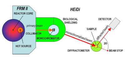
For the sake of putting this, rather detailed, chapter into its right context, we start with presenting an overview of neutron instrumentation. In particular, we will sketch a very simple neutron instrument, one example of which is shown in Figure xx--CrossReference--fig:heidiinstrument--xx. The neutrons we consider start their travel at the left of the figure: at the reactor. Then they are thermalized in the moderator, described in Moderators. Subsequently, the neutrons travel towards the right. At some instruments (not the one in Figure xx--CrossReference--fig:heidiinstrument--xx, the neutrons are transported by use of a neutron guide, which is described further in Neutron guide systems. At the center of the figure, neutrons with a particular wavelength are scattered by a monochromator, the details of which is described in Determining the incoming neutron wavelength. After the beam is being tailored by use of beam optics in Beam optical components, it finally impinges on the sample under study. The task of the instrument is now to determine how many neutrons are scattered in different scattering angles. This is measured by a movable neutron detector, which is described in Neutron detectors.
The instrument here shown is denoted a two-axis diffractometer. The two axes here represent the two places where the neutron changes direction (the monochromator and the sample), while the term diffractometer`` represent that the instrument deals with medium-to-high angle elastic scattering, known as diffraction. This was the first type of instrument constructed, and improved versions are still in use for the purpose of determining the atomic structure of crystals.
We now proceed with a much more detailed description of the individual components in neutron instrumentation.
Neutron guide systems
The earliest neutron scattering instruments used a beam of neutrons, extracted from the moderator through holes (or tunnels) in the shielding; also called a beam port. The neutron intensity from this type of beam port falls off in general as \(1/r^2\); for details: see the problem The beam port. This square law dependence dictates that neutron instruments of this type are placed close to the neutron source. Therefore they will suffer from a relatively high background from the source, e.g. from gamma-radiation, and from epithermal and fast neutrons.
In the early 1960's, a new concept was invented: The neutron guide. This is a neutron conducting channel, in principle equivalent to an optical fiber. The guide can extract a beam of neutrons from the moderator and deliver it at another point, further away from the neutron source[1]. Typical guide lengths are 10-100 m.
We will here take a closer look into neutron guide systems.
Guide reflectivity
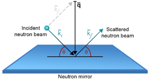
The neutron guide builds on the principle that surfaces of materials with positive values of the scattering length \(b\) show total reflection of thermal and cold neutrons under sufficiently small angles. At larger angles, the reflectivity falls off to zero very fast.
We define the critical angle, \(\theta_{\rm c}(\lambda)\), as the largest angle between the neutron path and the surface that still gives rise to total reflection. For a given material, the critical angle is proportional to the neutron wavelength. Following the equation for \(q\) from \(k\) and \(\theta\) and the corresponding figure from the Basics of neutron scattering page, the critical scattering vector is now given by
\begin{equation}\label{dummy613884281} q_{\rm c} = 2 k \sin(\theta_{\rm c} \,(\lambda)) \approx 4 \pi \dfrac{\theta_{\rm c}(\lambda)}{\lambda} , \end{equation}
when \(\theta_{\rm c}\) is given in radians. In general, \(q_{\rm c}\) is independent of \(\lambda\). For the standard guide material, Ni, the critical scattering vector is
\begin{equation}\label{dummy339440531} q_{\rm c, Ni} = 0.0217 {\rm Å}^{-1} . \end{equation}
Modern guides are made from multilayer material, usually with Ni as the outmost layer. This ensures total reflectivity up to \({q}_{\rm c, Ni}\). In addition, the reflectivity is non-zero up to a much higher scattering vector[2]
\begin{equation}\label{dummy799289935} {q}_{\rm c} = {m q}_{\rm c, Ni} .\, \end{equation}
One therefore often speaks about the \(m\)-value of a multilayer, e.g. an \(m=3\) guide. An example of a reflectivity profile for an $m=3.6$ guide is shown in Figure xx--CrossReference--fig:guide_R--xx (right). Typical values of \(m\) are 2-4, although mirrors with up to \(m=7\) can now be obtained. Multilayer guides can be purchased commercially, typically in pieces of 0.5 m length and cross sections of up to \(300 \times 300\) mm\(^2\)[3].
Experimental considerations
For neutrons of 1~Å and 10~Å wavelengths, the critical angles from Ni become \(\theta_{\rm c} = \eta_{\rm x} = 0.100^{\circ}\) and \(1.00^{\circ}\), respectively. This should be compared with the divergence requirements from present instruments, which is often in the range \(0.2^{\circ}\) to \(1^{\circ}\) Hence, neutron optics for 10~Å neutrons is a fairly easy task that can be performed with Ni mirrors, while shorter wavelengths present increasingly larger challenges, where higher \(m\)-value supermirrors are needed.
Straight guides
The "classical" and most often used guide system is the straight guide, where the guide cross section is constant along the full length of the guide. Typical sizes of cross sections from \(20 \times 20\) mm\(^2\) to \(120 \times 30\) mm\(^2\). Assuming the guide to be sufficiently long, the maximum divergence being transported through the guide is
\begin{equation}\label{dummy421761879} \theta_c = \eta_x = 0.100^\circ m \frac{\lambda}{[\mbox{Å}]}, \end{equation}
and the same for the \(y\)-direction. However, the effect of the supermirror decreases for large divergences (larger than \(\theta_{\rm c}\)), since neutrons will typically experience many reflections, and thus be attenuated by the reflectivity value to a high power.
In addition, we notice that the maximal volume of the available phase space in the guide is proportional to \(m^2 \lambda^2\). This explains why, until recently, guides were primarily used for cold neutrons and thermal instruments were most often placed at a beam port close to the moderator.
Curved guides
In practice, many constant-cross-section guides have sections which are slightly curved horizontally, with radii of the order \(R \approx 0.5-3\) km, while keeping the constant guide cross section. This is done in order to avoid direct line-of-sight from the moderator to the experiment, strongly reducing the number of hot and epithermal neutrons passing down the guide, which in turn minimizes the experimental background.
For an example of this guide cut-off, imagine a neutron which bounces alternatingly off the left and right walls of a guide with width \(w\). The guide curves to the left with the radius of curvature \(R_{\rm c}\). We consider the limiting case, where the neutron just glances off the left wall, \(2\theta = 0\), which gives the smallest possible scattering angle on the following reflection on the wall. Due to the curvature, the neutron will hit the right wall at an angle \(\theta = \sqrt{2w/R}\), corresponding to a scattering vector of \(q=(4 \pi/\lambda) \sqrt{2w/R}\). To scatter the neutron, we need \(q \leq m q_{\rm c, Ni}\). This leads to a condition for the zig-zag scattered neutrons
\begin{equation}\label{dummy1778420237} \lambda \geq \dfrac{4\pi}{mq_{\rm c,Ni}} \sqrt{\dfrac{2w}{R}} . \end{equation}
Using the typical values for a cold-neutron guide: \(m=2\), \(w=30\) mm, and \(R=2400\) m, we reach a lower cut-off for the transmitted neutrons: \(\lambda \geq 1.435\) Å. However, this is not the whole truth. Neutron paths exist, where the neutrons repeatedly scatter off the outer (in this case the left) wall only. The phase space of these so-called garland reflections trajectories is, however, much smaller than the regular left-right trajectories[4].
One way to overcome the garland reflections is to bend the guide first in one direction, then in the opposite. In this so-called S-shaped guide, the shortest wavelengths are completely eliminated.
Tapering guides
To increase the intensity of neutrons onto small samples, some existing guide systems have recently been equipped with focusing noses, which are often a linear (or curving) tapering piece of high-\(m\) supermirror guide that narrows the beam just before the sample. A well-designed nose will increase the number of neutrons hitting the sample, but according to the Liouville theorem, this comes at the expense of an increased beam divergence. In addition, the divergence profile from a tapering nose is often non-uniform, due to the difference in divergence between neutrons hitting the nose piece zero, one, or more times, respectively.
A full guide set-up using tapering guides is often known as a ballistic guide system. The guide starts with a linearly expanding section, followed by a straight (possibly curved) section, to end with a tapering converging nose. This guide system has the advantage that the expanding section decreases the divergence of the transmitted beam (at the cost of a decreased spatial density, according to Liouville). The lower divergence decreases the number of reflections and hence improves the guide transmission. At the nose piece, the neutron density again increases, with a corresponding increase of divergence [5].
Parabolic and elliptical guides
The parabolic guide system is an improved version of the ballistic guide. It consists of a parabolic expanding start, which ideally (for a point source) would make the beam completely parallel. Then follows a straight (possibly curved) section, and the guide system ends with a parabolic nose, which compresses the beam onto the sample[6][7]. For practical reasons, the guide is often parabolic in the \(x\) and \(y\) directions separately, so that the cross section of the guide is at any place rectangular.
The elliptical guide system consists of one fully elliptical piece with the moderator at (or close to) one focal point and the sample close to the other focal point. Ideally (for a point source), each neutron would then be reflected only once between moderator and sample, although recent work has shown that a finite size of the source would result in more than one reflection[8]. How simple it may sound, elliptical guides are only just being installed at the first instruments, with very good results, e.g. at the cold-neutron diffractometer WISH at ISIS[9]. In practice, also here, the guide cross section is rectangular, so that a general neutron would need a reflection both in the \(x\) and the \(y\)-direction.
Recent simulation work has shown that parabolic and elliptical guides have almost equal neutron transport properties over large distances (50 m and above), and that they outperform any other guide systems with transmissions of the phase space density close to the Liouville limit. However, there is yet no detailed experimental evidence for this result[5].
Shielding and shutters
To avoid neutron background outside the guide, a neutron absorbing material is being used to shield its outside. In addition, the gamma radiation produced by the neutron capture is shielded, using (typically) lead, steel, or concrete.
For safety reasons, the neutron beam can be blocked close to the guide entry by a primary beam shutter, which will be closed during long-term maintenance. The secondary beam shutter is placed at the guide end, close before the sample, and will be used for minor experimental interruptions, like change of sample. These shutters are made by a combination of materials that absorb both neutrons and gamma radiation.
- ↑ H. Maier-Leibnitz and T. Springer. J. Nucl. En. A/B, vol. 17, p. 217. (1963)
- ↑ F. Mezei, Communications in Physics 1, 81 (1976)
- ↑ Information from Swiss Neutronics Ltd. See http://swissneutronics.ch
- ↑ D.F.R. Mildner, Nucl. Instr. Meth. A, 290, 189 (1990)
- ↑ 5.0 5.1 K.H. Klenø, (in preparation, 2011)
- ↑ C. Schanzer et al, Nucl. Instr. Meth. A 529, 63 (2004)
- ↑ S. Mühlbauer et al, Physica B Cond. Matt. 385, 1247 (2006)
- ↑ L.D. Cussen et al, Nucl Instr. Meth. A 705, 121 (2013)
- ↑ L. Chapon et al, Neutron News 22:2, 25 (2011)
Beam optical components
We here present components that shape the neutron beam, typically between the moderator and the sample, but sometimes also between sample and detector.
Slits
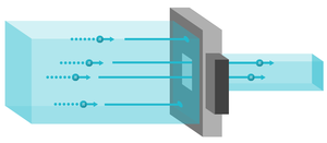
A slit, also known as a diaphragm, consists of a neutron-absorbing plate with a hole (rectangular or circular) for passage, as seen in Figure xx--CrossReference--fig:slit_instrument--xx. The slit limits the spatial size of the beam and is in particular used just before the sample, to eliminate neutrons that would not hit the sample.
Collimators
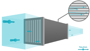
A horizontal Soller collimator consists of a number of thin, parallel, equidistant sheets (like every \(n\)'th page in a book) of a neutron absorbing material; see illustration on Figure xx--CrossReference--fig:collimator_instrument--xx. Hence, neutrons with "wrong" divergence are eliminated. The degree of collimation is presented as the FWHM of the transmission curve, understood as a plot of neutron intensity vs. angle between the collimator axis and the direction of a very well collimated beam. Usually, the collimation is in the range 10' to 120', where 60' (arc minutes) equals \(1^\circ\). The collimation of a Soller collimator is fixed, so a different collimator piece must be inserted in the beam to change the degree of collimation. The geometry of a Soller collimator is calculated in the problem The collimator.
The divergence of the neutron beam can also be reduced by two slits, placed a distance apart. Often, this will be a pair of pinholes, hence you speak about pinhole collimation. Alternatively, collimation can be performed in one direction only by a pair of rectangular slits, which are narrow in one direction. Often, one can control the pinhole diameter and distance, known as the collimation length, \(L_{\rm c}\), by inserting different pinholes at a number of fixed positions. The smallest practical collimation length is typically 1 m, while the longest can be up to 20 m, depending on the particular instrument.
Choppers
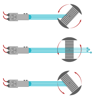
A chopper is a spinning device that alternately allows or blocks passage of neutrons.
The most simple chopper design is the disk chopper, which is basically a wheel covered by neutron absorbing materials, with slits cut to allow neutron passage at selected times. Disk choppers are being used for slow and medium time-scale events, down to 10-20 \(\mu\)s opening times. The fastest opening times, however, will require very narrow slits, and probably a combination of two closely spaced counter-rotating choppers. A typical disk chopper is shown in Figure xx--CrossReference--fig:choppers--xx.
Another type of chopper is the Fermi chopper, also shown in Figure xx--CrossReference--fig:choppers--xx. Here, a rotating collimator-like system ensures that neutrons are passing in short bursts only. Fermi choppers are typically used when very short opening times are required over a wide beam path.
Filters
In continuous source instruments, and for few pulsed-source instruments, filters are used to eliminate parts of the neutron wavelength spectrum. This is typically used to reduce unwanted background or to remove higher order Bragg scattering from monochromator crystals.
As one example, a block of pyrolytic graphite will allow passage of only a few selected energies (or wavelengths). One example for PG is 14.7~meV. Other types of filters consist of cooled block of Be or BeO, which transmit energies below 5.2~meV and 3.8~meV, respectively. The reason for this behaviour is that Bragg scattering will take place only for neutron wavelengths smaller than twice the largest lattice spacing in the material - and thus long-wavelength neutrons are directly transmitted without scattering. Details of this is left as an exercise for the reader; see Problem: The Be filter.
Experimental considerations
Beam optical elements in general serve to remove unwanted neutrons from the beam. These neutrons would in practice scatter from the sample in unexpected angles, or even off the sample environment. This scattering would contribute both to the overall background and to false, peaked signals, sometimes known as spurions.
Spurions may also come from multiple scattering events within the sample, which cannot be dealt with by beam optics.
Neutron detectors
We will here briefly touch upon the way neutrons are detected. The field of neutron detectors is vast and we refer the reader to more specialized literature for details[1].
Detection processes
Neutrons are typically detected by use of one of a handful nuclear reactions, which destroy the neutron as a result. Most used and most efficient is neutron capture of helium-3:
where the released energy, \(Q\), here is as low as 0.764 MeV [1]. However, also capture of \(^6\)Li and \(^{10}\)B is often being used.
The charged products from these nuclear reactions give rise to an electrical signal, which is subsequently amplified by charge amplification in an Ar gas under high voltage, as in a standard Geiger-Müller counter. The signal can then easily be detected.
Detectors may have just a single channel, or can be position sensitive in one or two dimensions. For particular applications, there exist area detectors with pixel sizes of around \(1 \times 1\) mm\(^2\) of sizes up to \(1 \times 1\) m\(^2\). Alternatively, one may use detector tubes with a diameter of 25 mm (one inch), being several meters long and linearly sensitive with a positioning accuracy of the order 5 mm. Helium-3 detectors of this type can detect up to \(10^5\) neutrons/second before saturating, depending on the speed of the amplifier electronics.
At pulsed neutron sources, the detector electronics can in addition record the detection time of the neutron with a precision of a few \(\mu\)s. This is crucial in order to utilize the time-of-flight information, as will be described later.
Monitors
For controlling the possibly varying intensities of the beam, monitors are used at all neutron instruments for normalization purposes. A monitor is a deliberately inefficient detector that interacts with only a small fraction of the neutron beam (of the order \(10^{-3}\) to \(10^{-4}\)). The counting efficiency is determined by the neutron absorption cross section and is hence proportional to \(\lambda\). Monitors are typically placed at the end of a guide, just before or after the sample.
Background and background levels
Background is the general notion for all neutron detector counts that do not arise from the physical process under investigation. One source of background comes from the sample itself, e.g.~incoherent scattering, and is difficult to discriminate against.
Another background source is the experimental environment, e.g.~neutrons from other experiments or fast neutrons from the source that penetrate a series of shielding barriers to be counted in the detector. This background can always be improved by additional shielding, by moving the instrument further away from the source, and by eliminating line-of-sight between moderator and sample. Fast-neutron background is of particular worry in spallation sources, due to the high energies in the spallation process itself.
At pulsed sources, the fast-neutron background can in some cases dominate even the strong elastical scattering from the sample. However, time-of-flight can be very efficiently used to discriminate these fast neutrons, since they will arrive almost immediately after the accelerator pulse has hit the target.
Example
At the end of a 30~m guide for the instrument RITA-II /CAMEA at the medium-flux source SINQ (PSI), the background count rates for a detector the size of a typical \(^3\)He detector tube, 150~mm high, 25~mm diameter, is 0.10~counts/minute with both the primary and secondary beam shutters closed [2]. This background is mostly due to electronic noise. During an experiment on the same instrument (both shutters open), the level of background not originating from the sample is around 0.2~counts/minute in the best cases.
- ↑ 1.0 1.1 See e.g. the home page: http://www.lanl.gov/quarterly/q_sum03/neutron_detect.shtml. We will soon find more references here...
- ↑ K. Lefmann et al. Realizing the full potential of a rita spectrometer. Physics B, 385-386:1083-1085, 2006.
Determining the incoming neutron wavelength
The famous Bragg law gives the relation between the wavelength, \(\lambda\), of radiation diffracting off a crystal with lattice spacing, \(d\), and the scattering angle, \(2\theta\):
\begin{equation} \label{eq:pre-bragg} n \lambda = 2 d \sin(\theta),\, \end{equation}
as presented on the Diffraction from crystals page - and derived thoroughly in the adjacent text. According to the Bragg law, in order to interpret the neutron signal at a particular angle, \(2\theta\) (meaning determine the lattice spacing, \(d\)), it is necessary to know the neutron wavelength, \(\lambda\). This is in practice done in two different ways:
- At continuous sources, the neutron beam is in general monochromatized
- At pulsed sources time-of-flight techniques are used to determine \(\lambda\).
We will here look in more detail on these two rather different methods.
Velocity selector
A neutron velocity selector is made from spinning absorbing blades, tilted from the main axis; see Figure xx--CrossReference--fig:velocityselector--xx. The neutron is transmitted only if its speed matches the selector rotation speed, so that the neutron never hits an absorbing blade. This arrangement will allow passage of neutrons with velocities close to a particular value; typical values are 2-20~Å , depending on selector rotation speed. The monochromatization is coarse; typically of the order of \(\Delta \lambda/\lambda \approx\)~10\%. Further details are left to the reader as an exercise, see Problem: Neutron velocity selector.
Monochromating a continuous neutron beam
To obtain a more precise determination of \(\lambda\), one uses another method: Bragg reflection from a crystal.
Consider again the Bragg law \eqref{eq:pre-bragg}, and imagine that now the lattice spacing, $d$, of the crystal is well known. In addition, the incident neutrons have a well-defined direction, but are polychromatic (a so-called white beam). In this case, only neutrons of certain wavelengths are scattered:
\begin{equation}\label{dummy291868694} \lambda = \dfrac{1}{n} 2 d \sin(\theta_{\rm m}) . \end{equation}
A crystal used in this way is called a monochromator, represented by the subscript "m" on the scattering angle \(2 \theta_{\rm m}\). The monochromator reflects a series of wavelengths, given by the integer, \(n\). The first order wavelength (\(n=1\)) is usually the desired one, while the higher order wavelengths are undesired. Typically, one will try to suppress the higher order neutrons by transmission filters and/or by guide geometries which provide low transmission for shorter wavelength neutrons.
An estimate of the monochromaticity of the diffracted beam is given by considering the uncertainty in the scattering angle, \(\delta\theta\), which is mostly determined by the experimental geometry: Guides, colllimators and slits. In contrast, the uncertainty in the lattice spacing is in many cases negligible. Performing uncertainty estimation (error propagation) of the Bragg law leads to
\begin{equation}\label{dummy2061579416} \delta\lambda = \dfrac{1}{n} 2 d \cos(\theta_{\rm m}) \delta\theta , \end{equation}
when \(\theta\) is calculated in radians. One often considers the relative precision of the wavelength determination:
\begin{equation}\label{dummy2099421147} \dfrac{\delta\lambda}{ \lambda} = \cot(\theta_{\rm m}) \delta\theta . \end{equation}
For \(90^\circ\) scattering (\(\theta = 45^\circ\)) and a typical divergence value \(\delta\theta = 0.5^\circ\), we reach \(\delta \lambda / \lambda \approx 1\) %.
Monochromators for thermal neutrons are often made from single crystals of Si, Ge, or Cu. For cold neutrons, pyrolytic graphite (PG) is the material of choice. As with most other large single crystals, monochromator materials often consist of many crystallites, which have a small, random misalignment with respect to a "common" direction. This mosaicity is often close to being Gaussian (i.e. a normal distribution) and affects the monochromatizing properties of the material strongly. A small mosaicity (10'-20') reflects a smaller amount of the incoming neutrons than larger mosaicities (30'-60'). On the other hand, a small mosaicity is beneficial if one requires a good resolution, i.e. a narrow wavelength distribution of the beam.
Experimental considerations
Monochromators for thermal neutrons are often made from single crystals of Si, Ge, or Cu. For cold neutrons, pyrolytic graphite (PG) is the material of choice.
Reflectivities of monochromators in Bragg condition depend both on the chosen material and on the neutron wavelength. Typical values range from 20 % to 80 %; the latter value achieved by PG with neutrons of \(\lambda > 4\) Å[1].
Time-of-flight analysis
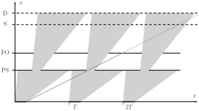
A completely different method of determining the neutron wavelength is by measuring the speed of the particle by time-of-flight analysis. Typical moderators at pulsed sources emit bursts of neutrons lasting \(\tau = 10-100\) \(\mu\)s separated by intervals of \(T \approx 20-100\) ms. The neutron start time at the moderator is thus very well defined. The neutron flight time from the moderator to the detector placed a distance, \(L\), from the moderator is
\begin{equation}\label{eq:TOF} t = \dfrac{L}{v} =\dfrac{m_{\rm N}}{2 \pi \hbar} L \lambda = \alpha \, L \, \lambda , \end{equation}
where \(\alpha = m_{\rm n}/h = 252.7\, \mu\) s/m/Å. The neutron wavelength can thus be determined directly from its time-of-flight. The uncertainty in the wavelength is in practice given by the pulse width \(\tau\) through
\begin{equation}\label{dummy133888562} \alpha L \delta \lambda \approx dt = \tau , \end{equation}
leading to
\begin{equation}\label{dummy954736455} \dfrac{\delta \lambda}{\lambda} = \dfrac{\tau}{\alpha L \lambda}. \end{equation}
Hence, to have a good relative wavelength resolution, one would use a long instrument (large \(L\)), use a source with a short pulse length \(\tau\), and/or use a long wavelength.
In diffraction experiments, one typically allows a broad wavelength band from the incident beam to hit the sample, and later determine the wavelength of the detected neutrons from the time-of-flight at the (time-sensitive) detectors. The reason for not allowing the full white beam in the incident beam is to avoid frame overlap. This happens when the slow neutrons from one pulse are overtaken by fast neutrons from the following pulse, creating ambigiuity in the data analysis. This is best illustrated on a time-of-flight diagram; see Figure xx--CrossReference--fig:TOF--xx. The spread in arrival times, \(\Delta t\), cannot be allowed to exceed the time between pulses, \(T\). From equation \eqref{eq:TOF}, the wavelength spread, \(\Delta \lambda\) is limited by
\begin{equation}\label{dummy1580353440} \alpha L \Delta \lambda < T . \end{equation}
The (broad) wavelength band is usually limited by disk choppers, which are in this connection denoted bandwidth definition choppers. Similar choppers are placed slightly longer downstream to prevent very slow neutrons from entering the bandwidth chopper from a wrong source pulse. Such choppers are called frame overlap choppers.
It is possible by fast spinning choppers to define a (nearly) monochromatic neutron beam from a pulsed source. This is used for inelastic neutron scattering and will be discussed later.
The ESS will have a very long pulse, \(\tau = 2.86\) ms. Hence, standard logic for pulsed sources does not apply, and many instrument concepts must be re-considered.
In particular, a shaping (shortening) of the pulse by choppers close the moderator is necessary for many instruments to avoid too large uncertainties in the determined value of \(\lambda\).
- ↑ T. Riste and K. Otnes, Nucl. Instr. Meth. 75, 197 (1969)
← Previous page: Neutron sources and moderators
→ Exercises: Exercises in Instrumentation
→ Next page: Small angle neutron scattering, SANS
