Reflectivity of stratified media
Materials with numerous thin film overlayers are known as stratified media. These materials have numerous interfaces. Reflectivity methods are very useful for characterizing the sharpness of the interfaces and the scattering length densities, which give rise to the refractive index of the layers.
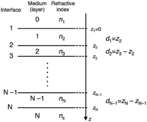
Calculating the reflectivity from stratified layers usually involve numbering the layers from the top of the sample to the bottom in the manner shown in Figure xx--CrossReference--reflectivityfig:multint--xx.
Equations \eqref{reflectivityeq:Fr} and \eqref{reflectivityeq:Ft} may be adapted to give the Fresnel reflection and transmission coefficients at an interface between layers \(j\) and \(j+1\), however this is insufficient to calculate the reflectivity. In addition to the reflected wave, the refracted wave, and the incident wave from above the interface horizon that were all described in the Reflection from a smooth, flat interface section, a second incident wave from below the interface horizon must also be considered. This second incident wave is the reflected wave from interfaces deeper in the sample. The only interface where the second incident wave does not need to be considered is the deepest. Beyond this interface the sample is assumed to be infinitely thick.
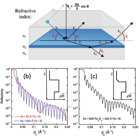
Figure xx--CrossReference--reflectivityfig:twointerfaceint--xx(a) shows a schematic example of the waves that must be considered when calculating the reflectivity from a single film on a substrate. The four waves that must be accounted for at the top interface between the refractive indices \(n_1\) and \(n_2\) are shown. The phase and the amplitude of the reflected wave from the bottom interface will be modified by the path length through the film and hence depends on the thickness, \(d\), of the film. The amplitude of the wave is thus modified by the factor
\begin{equation} a_j = \exp\left(-2ik_{jz}d_j\right). \label{reflectivityeq:Amp2} \end{equation}
The value of \(k_{jz}\) can be expressed as a function of the wavenumber in the topmost layer,
\begin{equation} k_{jz}=k_j\sqrt{\left(1-\cos^2\theta_j\right)}=k_1\sqrt{\left(\frac{n^2_j}{n^2_1}-\cos^2\theta_1\right)}. \label{reflectivityeq:krel} \end{equation}

The reflections from the different interfaces will interfere to give beats in the reflectivity. These beats are also known as `Keissig' fringes. Figure xx--CrossReference--reflectivityfig:twointerfaceint--xx(b) shows calculated examples of the reflectivity from a thin film of iron on silicon. The spacing between these fringes is approximately equal to \(2\pi\) divided by the thickness of the film. This approximation becomes much better far from the critical edge. Nevertheless, the figure shows that the 500 Å film, being ten times thicker than the 50 Å film, always has 10 minima in the Keissig fringes for every one of the thinner film.
Further overlayers lead to further interference, and the final reflectivity comes from a coherent summation of the reflected and transmitted waves at every interface. Separate thicknesses cannot be explicitly determined just by looking at the data, however if the thicknesses of the layers and their refractive indices are sufficiently different (i.e. the contrast between the layers is sufficiently large) then some information can be inferred. Figure xx--CrossReference--reflectivityfig:twointerfaceint--xx(c) shows a calculation for a thin oxide layer on a thicker iron layer. There are clearly two sets of beats present in the Keissig fringes and, from these, the thicknesses of the two layers can be inferred.
It is necessary to perform the complete summation in order to quantitatively analyse reflectivity data. There are two common methods of performing this calculation. The methods are mathematically identical.
The recursive method
This method is described by Parratt[1]. The layers of the sample are numbered as in Figure xx--CrossReference--reflectivityfig:multint--xx, and the Fresnel reflection coefficients for each interface, \(j\), are calculated after modifying equation \eqref{reflectivityeq:Fr} for reflection between layers \(j-1\) and \(j\),
\begin{equation} r_{j-1,j}=\frac{k_{\left(j-1\right)z}-k_{jz}}{k_{\left(j-1\right)z}+k_{jz}}. \label{reflectivityeq:ParrattrN} \end{equation}
The reflection from the \(N\)th interface is given by this Fresnel coefficient multiplied by the appropriate amplitude factor (equation \eqref{reflectivityeq:Amp2})
\begin{equation} R_{N-1,N}=a_{N-1}r_{N-1,N} . \label{reflectivityeq:ParrattRN} \end{equation}
This reflected wave is included in the calculation from the \(j=\left(N-1\right)\)th interface using a recursion formula
\begin{equation} R_{j-1,j}=a^2_{j-1}\left(\frac{R_{j,j+1}+r_{j-1,j}}{R_{j,j+1}r_{j-1,j}+1}\right). \label{reflectivityeq:ParrattrRj} \end{equation}
This recursion is continued to the first interface, noting that \(a_0 = 1\), and the sample reflectivity is given by
\begin{equation} {\cal{R}}=\left|R_{0,1}\right|^2. \label{reflectivityeq:ParrattRef} \end{equation}
The characteristic matrix method
This method is described by Born and Wolf[2] from the work of Abelès[3]. A matrix is written for each of the layers \(j=1...N-1\) in Figure xx--CrossReference--reflectivityfig:multint--xx, and has the form
\begin{equation} {\bf{M}}_j=\left[ \begin{array}{cc} \cos\left(k_{jz}d_j\right) & -\frac{i}{p_j}\sin\left(k_{jz}d_j\right) \\ -ip_j\sin\left(k_{jz}d_j\right) & \cos\left(k_{jz}d_j\right) \end{array} \right], \label{reflectivityeq:Mj} \end{equation}
with the definition that \(p_j=n_j\sin\theta_j\). Note that this can be expressed as a function of the wavenumber and angle at the topmost layer in a similar manner to \(k_jz\) in equation \eqref{reflectivityeq:krel}.
The matrices are then multiplied to give a final \(2 \times 2\) matrix,
\begin{equation} {\bf{M}}_{\cal{R}}={\bf{M}}_1{\bf{M}}_2...{\bf{M}}_{N-1}=\left[ \begin{array}{cc} M_{11} & M_{12} \\ M_{21} & M_{22} \end{array} \right]. \label{reflectivityeq:MR} \end{equation}
The resulting reflectivity coefficient is given by
\begin{equation} r=\frac {\left(M_{11}+M_{12}p_N\right)p_1-\left(M_{21}+M_{22}p_N\right)} {\left(M_{11}+M_{12}p_N\right)p_1+\left(M_{21}+M_{22}p_N\right)}. \label{reflectivityeq:rMat} \end{equation}
The matrix may also be expressed in terms of the Fresnel coefficients in equation \eqref{reflectivityeq:ParrattrN},
\begin{equation} {\bf{C}}_j=\left[ \begin{array}{cc} \exp{ik_{jz}d_j} & r_{j,j+1}\exp{ik_{jz}d_j} \\ r_{j,j+1}\exp{-ik_{jz}d_j} & \exp{-ik_{jz}d_j} \end{array} \right]. \label{reflectivityeq:Cj} \end{equation}
The matrices are then multiplied,
\begin{equation} {\bf{C}}_{\cal{R}}={\bf{C}}_1{\bf{C}}_2...{\bf{C}}_{N-1}=\left[ \begin{array}{cc} C_{11} & C_{12} \\ C_{21} & C_{22} \end{array} \right], \label{reflectivityeq:CR} \end{equation}
and the reflectivity coefficient is given by
\begin{equation} r=\frac{C_{21}}{C_{11}}. \label{reflectivityeq:rMatC} \end{equation}
In both cases the reflectivity \(\cal{R}\), is calculated from the reflectivity coefficient, \(r\), using equation \eqref{reflectivityeq:R}.
The relative merits of the two methods
Mathematically, the two methods are identical. The choice of which to use is essentially a question of which is the more efficiently written as computer code. Matrices, trigonometry, and the algebra of complex numbers are often complicated to code and slower to run when using low level computer languages, hence the recursive method is probably faster and easier to code. High level languages often have matrix algebra and complex numbers included in a software package, hence it may be easier to code reflectivity calculations when using the characteristic matrix method.
