Instruments for inelastic neutron scattering
In inelastic neutron scattering, it is necessary to determine both the initial and the final neutron energy, \(E_{\rm i}\) and \(E_{\rm f}\), in order to calculate the energy difference \(\hbar \omega = E_{\rm i} - E_{\rm f}\). This is done differently for continuous and pulsed neutron beams, as we shall see below.
Continuous source instrumentation, triple-axis spectrometer

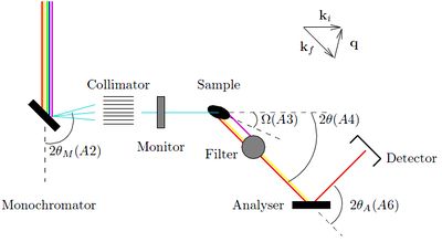
On instruments that uses a continuous beam of neutrons, it is necessary to directly select both \(E_{\rm i}\) and \(E_{\rm f}\), in order to determine the neutron energy transfer, \(\hbar\omega\). It is here customary to use Bragg diffraction from crystals for both purposes. Such a type of instrument is denoted a triple-axis spectrometer, since the neutron changes direction by scattering three times before being detected:
- A monochromator crystal selects \(E_{\rm i}\) of the incoming beam by Bragg scattering an angle \(2\theta_{\rm m}\).
- The sample scatters the beam by the angle \(2\theta\).
- The analyzer determines \(E_{\rm f}\) by Bragg scattering by an angle \(2\theta_{\rm a}\), in the same way as the monochromator.
The path of the neutron beam is kept in the same horizontal plane, also denoted the scattering plane. The build-up of the triple-axis spectrometer is shown in Figure xx--CrossReference--fig:TAS--xx.
By correct selection of the three scattering angles, and the sample rotation around a vertical axis, \(\omega\), the triple-axis spectrometer can be adjusted to any value of scattering vector, \(\bf q\), and energy transfer, \(\hbar \omega\), allowed by the inelastic scattering condition from the Basics of neutron scattering page. In fact, \(\bf q\) can only obtain values within the scattering plane. This means that there are 4 free angles to determine only 3 parameters: \(\hbar \omega\) and 2 dimensions of \(\bf q\). In practice, this ambigiuity is solved by fixing either \(E_{\rm i}\) or \(E_{\rm f}\) to a predetermined value.
A thorough presentation of how to perform experiments with a triple-axis spectrometer is given in Ref. [1] .
Experimental considerations
The 3 scattering angles, \(2\theta_{\rm m}\), \(2\theta\), and \(2\theta_{\rm a}\), are often denoted by the less-obvious symbols \(A2\), \(A4\), and \(A6\), respectively. The symbol \(A3\) denotes the sample rotation \(\omega\), while the symbols \(A1\) and \(A5\) denotes the rotation of monochromator and analyzer crystals, respectively.
The fixed value of \(E_{\rm i}\) or \(E_{\rm f}\) is often selected, knowing which devices can be used to eliminate higher-order scattering from monochromator and/or analyzer. As one example, a block of PG will allow passage of only a few selected energies (or wavelengths). One example for PG is 14.7 meV. Other types of filters consist of cooled block of Be or BeO, which transmit energies below 5.2 meV and 3.8 meV, respectively. See also the problem the Be filter.
Often, an experimental series consists of scans along a particular axis in \(({\bf q},\hbar\omega)\) space. One speak about constant-energy scans and constant-\(q\) scans. For the latter, it is costumary to use a constant \(E_{\rm f}\) for the scans and then measure each scan point until a constant count number in the beam monitor has been reached. Since the sensitivity of the monitor is proportional to wavelength, \(\lambda_{\rm i}\), the number of neutrons reaching the sample for each scan point is proportional to \(1/\lambda_{\rm i}\) - or to \(k_{\rm i}\). These facts causes the factor \(k_{\rm f}/k_{\rm i}\) in the final cross section (see this equation on the Scattering from lattice vibrations page) to be constant. Hence, the variation of this factor can be neglected, easing the subsequent data analysis.
Time-of-Flight inelastic spectrometers
On instruments at pulsed sources, one can utilize time-of-flight techniques as for diffraction. However, the time-of-flight cannot be used to determine both \(E_{\rm i}\) and \(E_{\rm f}\). Either the initial or final energy must be selected by other means, typically by Bragg reflection from crystals or by chopping the beam in short time pulses close to the sample. This leads to two essentially different types of spectrometer geometries:
- Direct geometry: The incoming neutrons are monochromatized by a chopper system, \(E_{\rm i}\) is fixed, and hits the sample in a short burst. Then, the time-of-flight is used to determine the variable \(E_{\rm f}\).
- Indirect geometry: The sample is hit by a "white" beam, and only outgoing neutrons with a particular energy is scattered by analyzer crystals on to the detector, i.e. \(E_{\rm f}\) is fixed. The time-of-flight is then used to determine \(E_{\rm i}\).
The advantages with time-of-flight spectroscopy are so large, that at many continuous sources one chooses to chop the beam close to the source, producing pulses by sacrificing more than 99 % of the neutrons coming through the guide system.
In later versions of these notes, there will be more material on time-of-flight spectrometers, including figures.
- ↑ G. Shirane and S.M. Shapiro and J.M. Tranquada, Neutron scattering with a Triple-Axis Spectrometer (Cambridge, 2002)