Reflection from a smooth, flat interface: Difference between revisions
ucph>Tommy No edit summary |
m (1 revision imported) |
(No difference)
| |
Latest revision as of 22:15, 18 February 2020
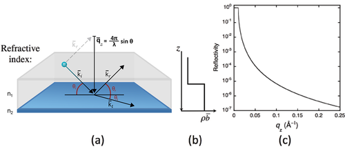
The potential for a wave changes at an interface between two media with different refractive indices. Through conservation of energy and momentum, the wave front at the interface splits in to a reflected part and a transmitted, or refracted, part. A schematic showing the effect is given in Figure xx--CrossReference--reflectivityfig:singleint--xx(a).
The incident wave is described by the wavevector \({\bf{k}}_i\) and subtends an angle \(\theta_i\) with the interface. Part of the wave is reflected at the interface to give a reflected wave vector, \({\bf{k}}_r\), with a subtended angle, \(\theta_r\). In the case of a perfectly flat interface the reflected angle equals the incident angle, \(\theta_i = \theta_r\), and the momentum transfer to the wave is normal to the interface, hereafter defined as the \(z\) direction. This is known as specular scattering.
The solution to the wave equations describing the reflected and transmitted waves depends on only one spatial direction, and this is the \(z\) direction. An exact algebraic solution is known, and it comes from matching the amplitudes and phases of the incident, reflected, and transmitted waves at the interface. Because the equations are one-dimensional, articles often show the refractive index, and more specifically the scattering length density, \(\rho\overline{b}\), as a function of the depth, \(z\), in the sample. These plots show the neutron potential, \(\overline{V}\). An example for a single interface is shown in Figure xx--CrossReference--reflectivityfig:singleint--xx(b).
Part of the wavefront may be transmitted with angle \(\theta_t\) to give a refracted wavevector, \({\bf{k}}_t\). The wavelengths and angles in the two media are related through Snell's Law
\begin{equation} n_1 \cos \theta_1 = n_2 \cos \theta_2. \label{reflectivityeq:Snell} \end{equation}
In the schematic shown in Figure xx--CrossReference--reflectivityfig:singleint--xx, \(\theta_1 = \theta_i\) and \(\theta_2 = \theta_t\).
The amplitudes of the two waves are given by the Fresnel formulae from classical optics theory. These give a reflectivity coefficient, \(r\), and transmission coefficient, \(t\), via the formulas
\begin{equation} r=\frac{n_1\sin\theta_1 - n_2\sin\theta_2}{n_1\sin\theta_1 + n_2\sin\theta_2}=\frac{k_{1z}-k_{2z}}{k_{1z}+k_{2z}}, \label{reflectivityeq:Fr} \end{equation} \begin{equation} t=\frac{2n_1\sin\theta_1}{n_1\sin\theta_1 + n_2\sin\theta_2} = \frac{2k_{1z}}{k_{1z}+k_{2z}}, \label{reflectivityeq:Ft} \end{equation}
where \(k_{jz} = k_j\sin{\theta_j}\) is the component of the wavevector, \({\bf{k}}_j\), along the direction normal to the interface, \(z\). The reflectivity, \(\cal R\), is defined as the reflected intensity, \(I_r\), divided by the incident intensity, \(I_0\). It is an absolute, unitless quantity which can be measured experimentally in a relatively straightforward manner. It is related to the Fresnel reflectivity coefficient through the equation
\begin{equation} {\cal{R}}\left(q_z\right) = \frac{I_r\left(q_z\right)}{I_0} = \left|r\right|^2. \label{reflectivityeq:R} \end{equation}
The reflectivity is a function of the momentum components of the incident and refracted waves normal to the interface, and is here expressed as a function of the momentum transfer of the reflected wave, \(q_z\). This momentum transfer is also normal to the interface and is equal to
\begin{equation} q_z=\frac{4\pi}{\lambda_i}\sin\theta_i . \label{reflectivityeq:qz} \end{equation}
The calculated reflectivity of a neutron beam at the interface between air and a block of silicon is shown in Figure xx--CrossReference--reflectivityfig:singleint--xx(c). It shows a remarkable feature at small \(q_z\) and has a characteristic behaviour at large \(q_z\) that warrant closer inspection.
Total reflection
If \(n_1 > n_2\), equation \eqref{reflectivityeq:Snell} shows that \(\theta_2\) can only be a real number for \(n_2 \ge n_1\cos\theta_1\). Beyond this limit the Fresnel reflection coefficient becomes imaginary and the reflectivity \({\cal{R}} = 1\). This commonly occurs for neutrons as equation \eqref{reflectivityeq:nTaylor} shows that the refractive index of a material with \(\overline{b}_c > 0\) is less than one, and is therefore less than the refractive index for a vacuum. All the neutrons below a critical \(q_z\) will therefore be reflected.
The critical edge below which total reflection is observed is given by
\begin{equation} q_c=\sqrt{16\pi\left(\rho_2\overline{b}_2-\rho_1\overline{b}_1\right)}. \label{reflectivityeq:Critqc} \end{equation}
Equation \eqref{reflectivityeq:Critqc} often expressed as a critical angle
\begin{equation} \theta_c=\lambda_1\sqrt{\frac{\rho_2\overline{b}_2-\rho_1\overline{b}_1}{\pi}}=\frac{\sqrt{4\pi\left(\rho_2\overline{b}_2-\rho_1\overline{b}_1\right)}}{k_1}. \label{reflectivityeq:CritAng} \end{equation}
Equations \eqref{reflectivityeq:Critqc} and \eqref{reflectivityeq:CritAng} are generic, and they become simpler when one of the media is air or vacuum for which \(\rho\overline{b} = 0\).
Reflection far from \(q_c\)
The approximation
\begin{equation} k_{1z}+k_{2z}\approx q_z \label{reflectivityeq:qzapprox} \end{equation}
is valid for \(q_z >> q_c\). Rewriting the reflectivity coefficient as
\begin{equation} r=\frac{k^2_{1z}-k^2_{2z}}{\left(k_{1z}+k_{2z}\right)^2}=\frac{q^2_c}{4\left(k_{1z}+k_{2z}\right)^2} \label{reflectivityeq:rq4} \end{equation}
leads to the observation that the reflectivity for large \(q_z\) will follow the relation
\begin{equation} {\cal{R}}\left(q_z\right) \propto q^{-4}_z. \label{reflectivityeq:Reflq4} \end{equation}
This expression is known as the Porod Law[1][2]. It also holds for reflection from interfaces that do not have total reflection. We also saw this as the large \(q\) limit of the small angle scattering cross section in the previous chapter. At these values of \(q\) the beam is scattering from the interfaces between the liquid used as the solute and the objects suspended in the solute. In effect, these data represent the reflectivity from spherically averaged single interfaces.
Reflectivity as a scattering phenomenon
When describing reflectivity in terms of the sum of scattering from nuclei, the cross-section is given by the square of the Fourier transform of the function used to describe the object that scatters the neutrons. In the case of reflectivity, the function describes the refractive index as a function of depth. An example for a single interface is given in Figure xx--CrossReference--reflectivityfig:singleint--xx(b).
The Fourier transform of this function is proportional to \(q^{-1}_z\). Squaring this function, and accounting for the surface area of the sample, gives the result that the cross-section is proportional to \(q^{-4}_z\), which is the Porod Law. The first Born approximation can therefore be used to calculate reflectivity far from \(q_c\).
However, a principal assumption of this formalism, known as the first Born approximation, is that the scattering must be weak. This is certainly not true as \(q_z \rightarrow 0\). Even in samples without a critical edge, \({\cal{R}}\left(0\right) = 1\). The scattering at small \(q_z\) is always strong, and the first Born approximation fails in this regime. It does not predict total reflection or the presence of a critical edge, and gives \({\cal{R}}\left(0\right) \rightarrow \infty\).
