Beam optical components: Difference between revisions
ucph>Tommy |
m (1 revision imported) |
(No difference)
| |
Latest revision as of 22:15, 18 February 2020
We here present components that shape the neutron beam, typically between the moderator and the sample, but sometimes also between sample and detector.
Slits
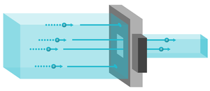
A slit, also known as a diaphragm, consists of a neutron-absorbing plate with a hole (rectangular or circular) for passage, as seen in Figure xx--CrossReference--fig:slit_instrument--xx. The slit limits the spatial size of the beam and is in particular used just before the sample, to eliminate neutrons that would not hit the sample.
Collimators
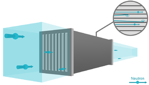
A horizontal Soller collimator consists of a number of thin, parallel, equidistant sheets (like every \(n\)'th page in a book) of a neutron absorbing material; see illustration on Figure xx--CrossReference--fig:collimator_instrument--xx. Hence, neutrons with "wrong" divergence are eliminated. The degree of collimation is presented as the FWHM of the transmission curve, understood as a plot of neutron intensity vs. angle between the collimator axis and the direction of a very well collimated beam. Usually, the collimation is in the range 10' to 120', where 60' (arc minutes) equals \(1^\circ\). The collimation of a Soller collimator is fixed, so a different collimator piece must be inserted in the beam to change the degree of collimation. The geometry of a Soller collimator is calculated in the problem The collimator.
The divergence of the neutron beam can also be reduced by two slits, placed a distance apart. Often, this will be a pair of pinholes, hence you speak about pinhole collimation. Alternatively, collimation can be performed in one direction only by a pair of rectangular slits, which are narrow in one direction. Often, one can control the pinhole diameter and distance, known as the collimation length, \(L_{\rm c}\), by inserting different pinholes at a number of fixed positions. The smallest practical collimation length is typically 1 m, while the longest can be up to 20 m, depending on the particular instrument.
Choppers
A chopper is a spinning device that alternately allows or blocks passage of neutrons.
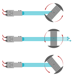
The most simple chopper design is the disk chopper, which is basically a wheel covered by neutron absorbing materials, with slits cut to allow neutron passage at selected times. Disk choppers are being used for slow and medium time-scale events, down to 10-20 \(\mu\)s opening times. The fastest opening times, however, will require very narrow slits, and probably a combination of two closely spaced counter-rotating choppers. A typical disk chopper is shown in Figure xx--CrossReference--fig:choppers--xx.
Another type of chopper is the Fermi chopper, also shown in Figure xx--CrossReference--fig:choppers--xx. Here, a rotating collimator-like system ensures that neutrons are passing in short bursts only. Fermi choppers are typically used when very short opening times are required over a wide beam path.
Filters
In continuous source instruments, and for few pulsed-source instruments, filters are used to eliminate parts of the neutron wavelength spectrum. This is typically used to reduce unwanted background or to remove higher order Bragg scattering from monochromator crystals.
As one example, a block of pyrolytic graphite will allow passage of only a few selected energies (or wavelengths). One example for PG is 14.7~meV. Other types of filters consist of cooled block of Be or BeO, which transmit energies below 5.2~meV and 3.8~meV, respectively. The reason for this behaviour is that Bragg scattering will take place only for neutron wavelengths smaller than twice the largest lattice spacing in the material - and thus long-wavelength neutrons are directly transmitted without scattering. Details of this is left as an exercise for the reader; see Problem: The Be filter.
Experimental considerations
Beam optical elements in general serve to remove unwanted neutrons from the beam. These neutrons would in practice scatter from the sample in unexpected angles, or even off the sample environment. This scattering would contribute both to the overall background and to false, peaked signals, sometimes known as spurions.
Spurions may also come from multiple scattering events within the sample, which cannot be dealt with by beam optics.


