Introduction to imaging
In neutron imaging the interior structure of a sample is visualised in real space with a resolution of the order 10-100 micrometer, unlike scattering experiments where the information is obtained in reciprocal space and is an average over the sample volume illuminated. Like the scattering techniques, the imaging method is non-destructive and has been used in a wide variety of applications ranging from inspection of objects of preservation interest (e.g. cultural heritage) and industrial components to visualization and quantification of interior dynamical processes (e.g. water flow in operational fuel cells).
Neutron imaging is in general restricted to take place at large scale facilities. One example is the ICON beamline at SINQ, PSI, where a schematic illustration is shown in Figure xx--CrossReference--fig:icon--xx[1].
One aspect of imaging is radiography. Here, a two-dimensional (2D) map of the transmitted neutrons are obtained at the detector screen, similar to X-ray radiography known from the hospitals. The Radiography section deals with the instrumentation needed for neutron imaging, including spatial and temporal image resolution and the detector system. Another aspect of imaging is computed tomography (CT), which is well known for X-rays, but also feasible with neutrons. Here, the sample is rotated around an axis perpendicular to the beam direction and radiographic projection images are obtained stepwise from different view angles. These images are combined mathematically to give the three-dimensional (3D) map of the attenuation coefficient in the interior of the sample. This will be explained in detail in Computed tomography section.
Attenuation


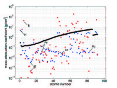
The neutron attenuation can happen either by absorbtion or scattering. The corresponding cross sections are given in the cross section table on the Basics of neutron scattering page for some elements. In Figure xx--CrossReference--fig:abs_Xn--xx, we show the attenuation coefficient for all elements as a function of atomic number for thermal neutrons (25 meV), compared to the absorption cross section for X-rays (100 keV). Whereas neutrons interact with the nuclei of matter, X-rays interact with its electrons. With X-rays, the attenuation is higher, the higher the electron density (the higher the atomic number). There is no such regular correlation for the interaction between neutrons and matter, and hence the attenuation coefficients are irregularly distributed independent of the atomic number. In the figure the mass attenuation coefficients are given as \({\mu}/{\rho}\), with \(\rho\) being the density. The linear attenuation coefficient, \(\mu\), has the unit of reciprocal length. The relationship between the attenuation coefficient and the cross section is given by
\begin{equation} \frac{\mu}{\rho}=\frac{N_a}{M}\sigma \end{equation}
where \(N_a\) is Avogadros number, \(M\) is the molar mass, and \(\sigma\) is the total cross section.
It is seen from the figure that the light elements, such as hydrogen and boron, have a very low absorption cross section for X-rays while they strongly scatter (blue) or absorb (red) neutrons. In contrast, many important metals can much easier be penetrated by neutrons than by X-rays (Al, Fe, Sn, and Pb are marked in Figure xx--CrossReference--fig:abs_Xn--xx as examples).
Neutron imaging can in many cases be used as a complementary technique to the X-ray radiography. This is illustrated in Figure xx--CrossReference--fig:abs_camera--xx, which shows a radiographic image of an analog camera obtained with X-rays (a) and neutrons (b). In the X-ray image the metal parts from the battery are attenuating strongly, but seem totally transparent to neutrons. Neutrons, on the other hand, display strong contrast to image the lighter polymer (plastic) parts containing significant amounts of hydrogen. Because neutrons interact directly with the nuclei, the attenuation coefficient differs even between isotopes (unlike the X-ray attenuation), making is possible to distinguish for example the water types: hydrogen oxide (normal water, H\(_2\)O) and deuterium oxide (heavy water, D\(_2\)O), because the total cross section for hydrogen is 40 times that of deuterium, see the cross section table on the Basics of neutron scattering page.